PRODUCT DESIGN
8
ROOF C URB I NSTALLATIONS O NLY:
Curb installations must comply with local codes and should
be done in accordance with the established guidelines of the
National Roofing Contractors Association.
Proper unit installation requires that the roof curb be firmly
and permanently attached to the roof structure. Check for
adequate fastening method prior to setting the unit on the
curb.
Full perimeter roof curbs are available from the factory and are
shipped unassembled. Field assembly, squaring, leveling
and mounting on the roof structure are the responsibility of the
installing contractor. All required hardware necessary for the
assembly of the sheet metal curb is included in the curb
accessory.
WARNING
T
O PREVENT POSSIBLE EQUIPMENT DAMAGE, PROPERTY DAMAGE, PERSONAL
INJURY OR DEATH, THE FOLLOWING BULLET POINTS MUST BE OBSERVED
WHEN INSTALLING THE UNIT.
• Sufficient structural support must be determined prior to
locating and mounting the curb and package unit.
• Ductwork must be constructed using industry guide-
lines. The duct work must be placed into the roof curb
before mounting the package unit. Our full perimeter
curbs include duct connection frames to be assembled
with the curb. Cantilevered type curbs are not available
from the factory.
• Curb insulation, cant strips, flashing and general roofing
material are furnished by the contractor.
The curbs must be supported on parallel sides by roof
members. The roof members must not penetrate supply and
return duct opening areas as damage to the unit might occur.
NOTE: The unit and curb accessories are designed to
allow vertical duct installation before unit placement. Duct
installation after unit placement is not recommended.
A
LL
CURBS
LOOK
SIMILAR
. T
O
AVOID
INCORRECT
CURB
POSITIONING
,
CHECK
JOB
PLANS
CAREFULLY
AND
VERIFY
MARKINGS
ON
CURB
ASSEMBLY
. I
NSTRUCTIONS
MAY
VARY
IN
CURB
STYLES
AND
SUPERSEDES
INFORMATION
SHOWN
.
CAUTION
See the manual shipped with the roof curb for assembly and
installation instructions.
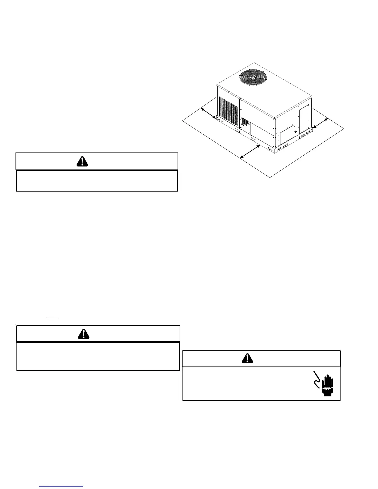
CLEARANCES
24”
Min.*
24”
Min.*
36” Min.
*
Unit Clearances
*In situations that have multiple units, a 48” minimum clearance
is required between the condenser coils.
Adequate clearance around the unit should be kept for safety,
service, maintenance, and proper unit operation. A total
clearance of 75” on the main control panel side of the unit is
recommended to facilitate possible fan shaft, coil, electric
heat and gas furnace removal. A clearance of 48” is
recommended on all other sides of the unit to facilitate
possible compressor removal, to allow service access and to
insure proper ventilation and condenser airflow. The unit must
not be installed beneath any obstruction. The unit should be
installed remote from all building exhausts to inhibit ingestion
of exhaust air into the unit fresh air intake.
PROTRUSION
Inspect curb to ensure that none of the utility services
(electric) routed through the curb protrude above the curb.
ELECTRICAL WIRING
HIGH VOLTAGE!
D
ISCONNECT
ALL
POWER
BEFORE
SERVICING
OR
INSTALLING
THIS
UNIT
. M
ULTIPLE
POWER
SOURCES
MAY
BE
PRESENT
. F
AILURE
TO
DO
SO
MAY
CAUSE
PROPERTY
DAMAGE
,
PERSONAL
INJURY
OR
DEATH
.
WARNING
 Loading...