PRODUCT DESIGN
10
AREAS W ITHOUT C ONVENIENCE O UTLET
It is recommended that an independent 115V power source
be brought to the vicinity of the roof top unit for portable lights
and tools used by the service mechanic.
NOTE: Refer to local codes for requirements. These outlets
can also be factory installed.
UNITS INSTALLED ON ROOF TOPS
Main power and low voltage wiring may enter the unit through
the condenser end of unit or through the roof curb. Install
conduit connectors at the desired entrance locations. Exter-
nal connectors must be weatherproof. All holes in the unit
base must be sealed (including those around conduit nuts) to
prevent water leakage into building. All required conduit and
fittings are to be field supplied.
Supply voltage to roof top unit must not vary by more than
10% of the value indicated on the unit data plate. Phase
voltage unbalance must not exceed 2%. Contact your local
power company for correction of improper voltage or phase
unbalance.
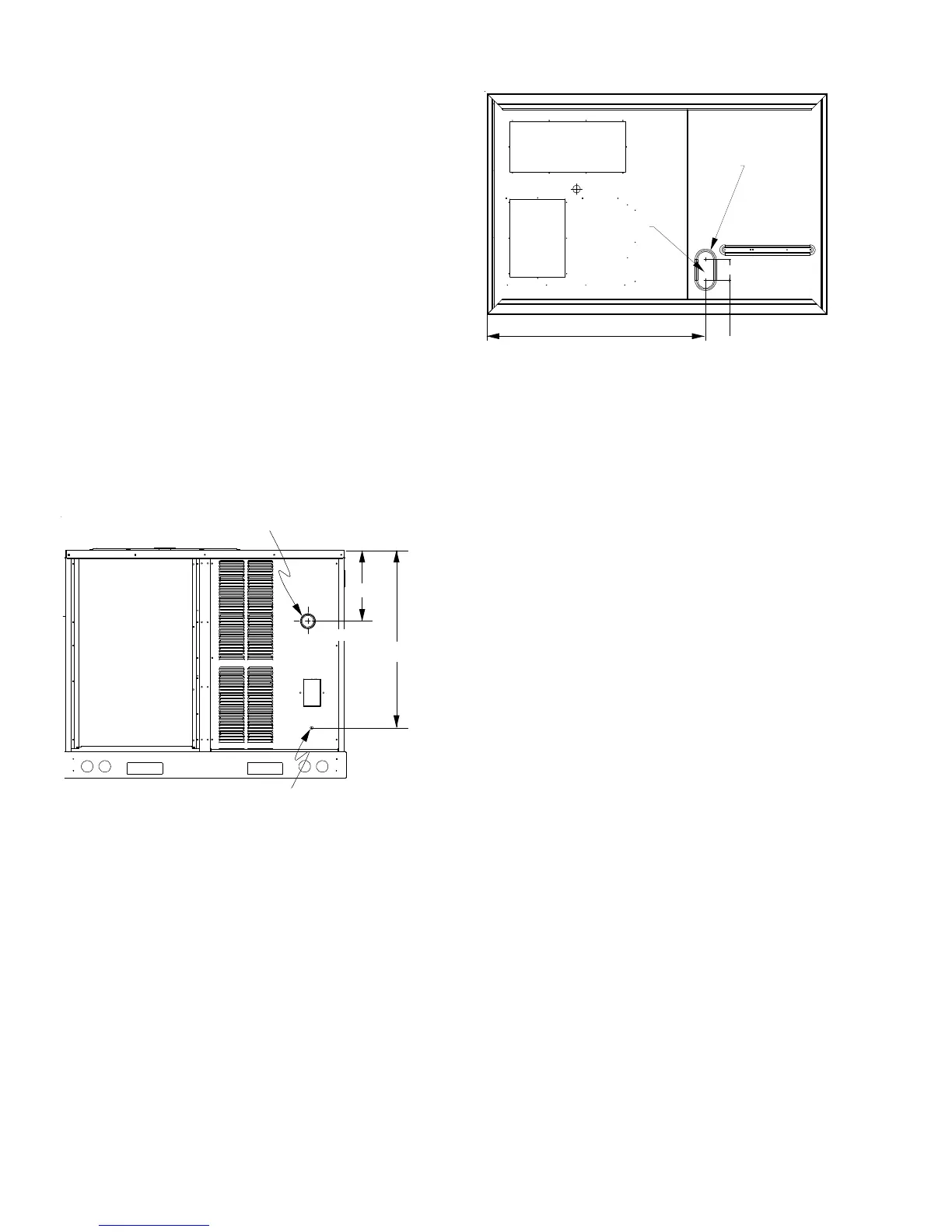
HIGH VOLTAGE ENTRANCE
LOW VOLTAGE ENTRANCE
1:4
30 1/4”*
12 3/8”
(REMOVE PLUG)
* (6 Ton - 34 1/4”)
4 1/2”
47 1/2”
7 1/2”
POWER THRU
THE CURB
3.5 DIA.
Electrical Entrance and Thru Curb
Unit is equipped with a Low Voltage Terminal Block and has
Single Point wiring to the contactor or power block, if
equipped.
LOW V OLTAGE C ONTROL W IRING
1. A 24V thermostat must be installed for unit operation. It
may be purchased with the unit or field -supplied. Ther-
mostats may be programmable or electromechanical as
required.
2. Locate thermostat or remote sensor in the conditioned
space where it will sense average temperature. Do not
locate the device where it may be directly exposed to
supply air, sunlight or other sources of heat. Follow
installation instructions packaged with the thermostat.
3. Use #18 AWG wire for 24V control wiring runs not
exceeding 75 feet. Use #16 AWG wire for 24V control
wiring runs not exceeding 125 feet. Use #14 AWG wire
for 24V control wiring runs not exceeding 200 feet. Low
voltage wiring may be National Electrical Code (NEC)
Class 2 where permitted by local codes.
4. Route thermostat wires from sub-base terminals to the
unit. Control wiring should enter through the condenser
panel opening or through curb indicated in “Electrical
Entrance” figure. Connect thermostat and any accessory
wiring to low voltage terminal block TB1 in the main
control box.
NOTE: Field-supplied conduit may need to be installed
depending on unit/curb configuration. Use #18 AWG solid
conductor wire whenever connecting thermostat wires to
terminals on sub-base. DO NOT use larger than #18 AWG
wire. A transition to #18 AWG wire may be required before
entering thermostat sub-base.
NOTE: Refer to unit wiring diagrams for thermostat
hookups.
 Loading...