SYSTEM OPERATION
13
CIRCULATING AIR AND FILTERS
DUCTWORK
The supply duct from the unit through a wall may be installed
without clearance. However, minimum unit clearances must
be maintained (see “Clearances” section). The supply duct
should be provided with an access panel large enough to
inspect the air chamber downstream of the heat exchanger.
A cover should be tightly attached to prevent air leaks.
Ductwork dimensions are shown in the roof curb installation
manual.
If desired, supply and return duct connections to the unit may
be made with flexible connections to reduce possible unit
operating sound transmission.
VENTING
NOTE: Venting is self-contained.
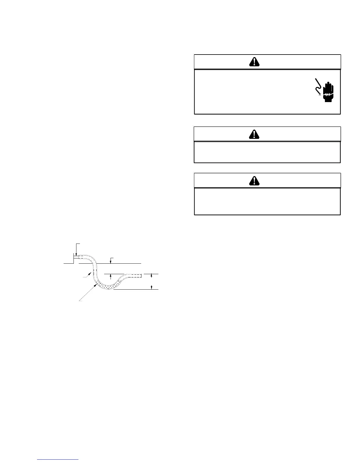
CONDENSATE DRAIN CONNECTION
CONDENSATE D RAIN C ONNECTION
A 3/4” female NPT drain connection is supplied on the end of
the unit and bottom of the drain pan for condensate piping. An
external trap must be installed for proper condensate drain-
age.
DRAIN
CONNECTION
UNIT 2" MINIMUM
FLEXIBLE
TUBING-HOSE
OR PIPE
3" MINIMUM
A POSITIVE LIQUID
SEAL IS REQUIRED
Drain Connection
Install condensate drain trap as shown. Use 3/4" drain line
and fittings or larger. Do not operate without trap.
HORIZONTAL D RAIN
Drainage of condensate directly onto the roof may be accept-
able; refer to local code. It is recommended that a small drip
pad of either stone, mortar, wood or metal be provided to
prevent any possible damage to the roof.
CLEANING
Due to the fact that drain pans in any air conditioning unit will
have some moisture in them, algae and fungus will grow due
to airborne bacteria and spores. Periodic cleaning is neces-
sary to prevent this build-up from plugging the drain.
STARTUP, ADJUSTMENTS, AND CHECKS
HIGH VOLTAGE!
OND
THE
FRAME
OF
THIS
UNIT
TO
THE
BUILDING
ELECTRICAL
GROUND
BY
USE
OF
THE
GROUNDING
TERMINAL
PROVIDED
OR
OTHER
ACCEPTABLE
MEANS
. D
ISCONNECT
ALL
POWER
BEFORE
SERVICING
OR
INSTALLING
THIS
UNIT
.
T
O
AVOID
PERSONAL
INJURY
OR
DEATH
DUE
TO
ELECTRICAL
SHOCK
,
B
WARNING
T
O
PREVENT
PROPERTY
DAMAGE
OR
PERSONAL
INJURY
, D
O
NOT
START
THE
UNIT
UNTIL
ALL
NECESSARY
PRE
-
CHECKS
AND
TESTS
HAVE
BEEN
PERFORMED
.
CAUTION
MOVING MACHINERY HAZARD!
T
O
PREVENT
POSSIBLE
PERSONAL
INJURY
OR
DEATH
,
DISCONNECT
POWER
TO
THE
UNIT
AND
PADLOCK
IN
THE
“OFF”
POSITION
BEFORE
SERVICNG
FANS
.
WARNING
CONTRACTOR R ESPONSIBILITY
The installing contractor must be certain that:
• All supply and return air ductwork is in place, properly
sealed, and corresponds with installation instructions.
• All thermostats are mounted and wired in accordance
with installation instructions.
• All electric power, all gas, hot water or steam line
connections, and the condensate drain installation
have been made to each unit on the job. These main
supply lines must be functional and capable of operat-
ing all units simultaneously.
• Requirements are met for venting and combustion air.
• Air filters are in place.
• Input rate and temperature rise are adjusted per rating
plate.
• Return air temperature is maintained between 55°F
(13°C) and 80°F (27°C).
ROOF C URB I NSTALLATION C HECK
Inspect the roof curb for correct installation. The unit and curb
assembly should be level. Inspect the flashing of the roof
mounting curb to the roof, especially at the corners, for good
workmanship. Also check for leaks around gaskets. Note
any deficiencies in a separate report and forward to the
contractor.
 Loading...