SYSTEM OPERATION
15
6. Slowly lower the cooling temperature until the unit starts.
The compressor, blower and fan should now be operat-
ing. Allow the unit to run 10 minutes, make sure cool air
is being supplied by the unit.
7. Turn the temperature setting to the highest position,
stopping the unit. The indoor blower will continue to run
for 65 seconds.
8. Turn the thermostat system switch to “OFF” and discon-
nect all power when servicing the unit.
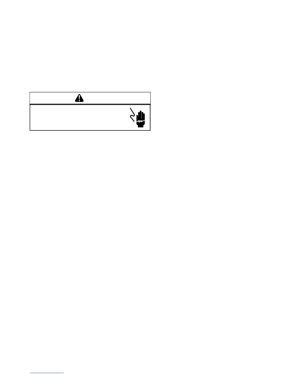
HIGH VOLTAGE!
D
ISCONNECT
ALL
POWER
BEFORE
SERVICING
OR
INSTALLING
THIS
UNIT
. M
ULTIPLE
POWER
SOURCES
MAY
BE
PRESENT
. F
AILURE
TO
DO
SO
MAY
CAUSE
PROPERTY
DAMAGE
,
PERSONAL
INJURY
OR
DEATH
.
WARNING
HEAT PUMP
9. Check the cooling mode for the heat pump in the same
manner as above. The reversing valve is energized when
the thermostat is placed in the cooling position. A
clicking sound should be noticeable from the reversing
valve. By lowering the temperature setting to call for
cooling, the contractor is energized. The compressor,
blower and fan should then be running. After the cooling
mode is checked out, turn the thermostat system switch
to “OFF”.
10. Turn the thermostat system switch to “HEAT” and fan
switch to “AUTO”.
11. Slowly raise the heating temperature setting. When the
heating first stage makes contact, stop raising the
temperature setting.. The compressor, blower and fan
should now be running with the reversing valve in the de-
energized (heating) position. After giving the unit time to
settle out, make sure the unit is supplying heated air.
12. If the outdoor ambient is above 80°F, the unit may trip on
its high pressure cut out when on heating. The compres-
sor should stop. The heating cycle must be thoroughly
checked, so postpone the test to another day when
conditions are more suitable but-DO NOT FAIL TO TEST.
If the outdoor ambient is low and the unit operates
properly on the heating cycle, you may check the
pressure cutout operation by blocking off the indoor
return air until the unit trips.
13. If unit operates properly in the heating cycle, raise the
temperature setting until the heating second stage makes
contact. Supplemental resistance heat, if installed should
now come on. Make sure it operates properly.
NOTE: If outdoor thermostats are installed the outdoor
ambient must be below the set point of these thermo-
stats for the heaters to operate. It may be necessary to
jumper these thermostats to check heater operation if
outdoor ambient is mild.
14. For thermostats with emergency heat switch, return to
step 11. The emergency heat switch is located at the
bottom of the thermostat. Move the switch to emergency
heat. The heat pump will stop, the blower will continue to
run, all heaters will come on and the thermostat emer-
gency heat light will come on.
15. If checking the unit in the wintertime, when the outdoor
coil is cold enough to actuate the defrost control, observe
at least one defrost cycle to make sure the unit defrosts
completely.
HEAT PUMP OPERATION
COOLING CYCLE
When the heat pump is in the cooling cycle, it operates
exactly as a Summer Air Conditioner unit. In this mode, all the
charts and data for service that apply to summer air condition-
ing apply to the heat pump. Most apply on the heating cycle
except that “condenser” becomes “evaporator”, “evaporator”
becomes “condenser”, “cooling” becomes “heating”.
HEATING CYCLE
The heat pump operates in the heating cycle by redirecting
refrigerant flow through the refrigerant circuit external to the
compressor. This is accomplished with through the reversing
valve. Hot discharge vapor from the compressor is directed to
the indoor coil (evaporator on the cooling cycle) where the
heat is removed, and the vapor condenses to liquid. It then
goes through the expansion device to the outdoor coil
(condenser on the cooling cycle) where the liquid is evapo-
rated, and the vapor goes to the compressor.
When the solenoid valve coil is operated either from heating
to cooling or vice versa, the piston in the reversing valve to the
low pressure (high pressure) reverse positions in the revers-
ing valve.
The following figures show a schematic of a heat pump on the
cooling cycle and the heating cycle. In addition to a reversing
valve, a heat pump is equipped with an expansion device and
check valve for the indoor coil, and similar equipment for the
outdoor coil. It is also provided with a defrost control system.
The expansion devices are flowrator distributors and perform
the same function on the heating cycle as on the cooling
cycle. The flowrator distributors also act as check valves to
allow for the reverse of refrigerant flow.
 Loading...