Home
Daikin
Control Panel
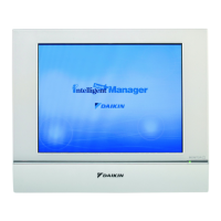
DCM601A51
Daikin DCM601A51 Technical Data
4
of 1
of 1 rating
405 pages
Give review
Manual
Specs
To Next Page
To Next Page
Loading...
T
echnical Data
EEDEN13-721208
Intelligent T
ouch
Manager
Air Conditioners
2
Table of Contents
Default Chapter
1
Technical Data
1
Table of Contents
3
Part 1 Intelligent Touch Manager
5
Central Control
8
Layout View
8
List View
8
Simple Operation
8
Air Conditioning Control Using a PC
9
Comprehensive Management History
9
Easy Access to a Wide Range of Menus
9
Remote Access
9
Interlock Variety
10
Automatic Control
10
Automatic Operation for the Entire Year
10
Comfortable
11
Emergency Stop for Localised Fire Protection Areas
11
Comparison from the Previous Year
12
Daily Energy Consumption
12
Energy Management
12
Energy Saving Control Assisted by Energy Navigator
12
Troubleshooting
14
Scalability
15
Specifications
16
Main Specifications
18
Part 2 Fundamental of DIII-NET
19
Design of DIII-NET
20
Features of DIII-NET
20
DIII-NET Design Standard
21
Terminal Number
21
Detail of Outdoor Unit Terminal No.
21
Connection Method
22
Correct Wiring
22
Incorrect Wiring Example
23
Wiring Example
26
Example of Control Wiring
26
Wiring Length
28
Recommendation of Installation DIII-NET Expander Adaptor
28
Wiring Specifications of DIII-NET
28
Unit and Group
30
Number of Connectable Units
31
Number of Units to be Connected [VRV] (Supplementary Explanation)
31
Connection of Devices Other than VRV
32
Group and Zone
33
Group Address
33
Setting Group Address for Centralized Control
34
Wired Remote Controller
34
Navigation Remote Controller
34
Wireless Remote Controller
35
Simplified Remote Controller
36
Heat Reclaim Ventilator Wired Remote Controller
37
Centralized Control Equipments Which Can Use with Intelligent Touch Manager
38
Under Centralized Control
39
Error Code on Initial Setting and Wiring Troubles
39
Appendix
39
Part 3 Power Proportional Distribution (PPD)
41
PPD Design Guide
42
Confirmation of Watthour Meter
42
System Architecture
42
Calculation Condition
43
Design Precautions
43
In Case Power Consumption of Indoor Unit to be Included
43
Remote Controller Group
43
Calculation of Electric Power
44
Setting of each Electric Power Group
44
The Reason Why VRV Heat Recovery Must Not be Included
45
Count Method
46
Explanations of Power Proportional Distribution
46
What Is the Power Proportional Distribution (PPD)
46
Counting the Electricity at the Stopped Condition of the Unit
47
Case of Arising Error
48
Cause of Error
48
Count Accuracy
48
The Way to Reduce Errors
49
Notes
50
Reference Material
51
Case Examples
51
Q & a
54
What Situations and What Operations Cause Loss of PPD Result?
54
Part 4 Adaptor
55
Adaptor for Air-Conditioning System
56
Wiring Adaptor for Electrical Appendices (1) <KRP2A61 / KRP2A62 / KRP2A53
56
Ceiling Mounted Cassette Corner Type
57
Installation
57
Part Names and Functions
57
Electric Wiring Work and Initial Setting
59
Wiring to the Adaptor
59
Initial Setting
60
Remote Control Input
60
Setting Control Mode Selector Switch (RS1)
61
Timing Chart for each Control Mode by Pulse Input
63
Temperature Setting Input
64
Output Display Signals
65
Wiring Adaptor for Electrical Appendices (2) <KRP4AA51 / KRP4AA52 / KRP4AA53 / KRP4A54
66
Central Priority
74
Remote Controller Acceptance / Rejection
74
Remote Controller Rejection
74
Timing Chart for each Control Mode by Momentary Input
74
Interface Adaptor for Skyair Series <DTA102A52
76
Electric Wiring Work
80
Interface Adaptor for Skyair <DTA112BA51
80
Installation and Electric Wiring
81
Central Control Adaptor Kit <DTA107A55
82
Interface Adaptor for DIII-NET Use (RA) <KRP928B2S
87
Contact Input Function Settings
89
For Overseas / Japanese Unit Setting
89
Settings When Recovering from a Power Outage
89
Switch Settings
89
Control Codes
90
Read Operating / Error Display Signal
90
Adaptor for Wiring <KRP1B61 / KRP1BA54, B56, BA57, BA59 / KRP1C63, C64
91
External Control Adaptor for Outdoor Unit <DTA104A61 / DTA104A62 / DTA104A53
99
Demand Input Terminal
104
Input Signal
104
Low-Noise Input Terminal
104
Outside Wiring Specifications
104
To Set the Outdoor Unit’s COOL/HEAT Address to No. 15
106
To Set the Outdoor Unit’s Demand Address to No. 7
106
Cool / Heat Selector <KRC19-26A
107
Installation Point
107
DIII-NET Expander Adaptor <DTA109A51
108
Adaptor for Other Equipment
112
Wiring Adaptor for Other Air Conditioners <DTA103A51
112
DI Unit <DEC101A51
116
DI Unit <DEC101A51
117
Restrictions in Continuous Installation
120
To Remove Front Panel
120
Wiring Lead-In
121
Electric Wiring Connection
124
Wiring Procedure
124
Wiring with Facility Equipment
124
Power Supply & Earth Wiring
124
Dio Unit <DEC102A51
125
Operation Output
126
Operation Input
127
Abnormal Input
127
DS2 Setting
135
DS4-1 Setting
135
SS1 Setting
136
TP1 Setting
136
Part 5 Installation Manual
137
Safety Precautions
138
Intelligent Touch Manager
140
Before Installation
142
Checking that All Accessories Are Included
142
Understanding External Dimensions
143
Angle Bracket
144
Frame Bracket
144
Rear Face
145
Understanding Where Terminals and Switches Are Located
145
Front Panel
146
Routing of Cables
147
Side Face
147
Determining Installation Place
148
Environmental Conditions
148
Installation Place and Mounting Direction
148
Required Space
148
Connecting an Emergency Stop Input Device or Electric Energy Meters
149
Connecting DIII-Net-Compatible Air Conditioning Equipment
149
Connecting Itm Plus Adaptors
149
Connecting Power Supply
149
Connection
149
Removing Terminal Cover from Rear Face
149
Terminals Location and Conceptual Connection Diagram
150
Precautions for Using Multiple Centralized Controllers
151
Requirements that Must be Met
151
Connecting a LAN Cable
152
Connecting I/O Module
154
Address Setup
155
Connecting an Emergency Stop Input Device or Electric Energy Meters
155
Connecting Itm Plug Adaptors
157
Connecting Power Supply
158
Installation
160
Parts to be Used
160
Wall Mounting
160
English
161
Flush Wall Mounting
161
Wall Opening Dimensions
162
Securing Frame Bracket and Angle Brackets
163
Installation Manual 3P291714-1
164
Installing Intelligent Touch Manager Body
164
Removing Frame
164
Direct Mounting to Control Enclosure
165
Basic Setup
167
Powering on Data Backup Battery
167
Powering on Intelligent Touch Manager and Air Conditioners
167
Setting up Display Language
168
Setting up Locale
168
Setting Current Time and Daylight Saving Time
169
Setting Time Zone
169
Assigning a DIII-NET Address for each Air Conditioner
170
Confirming Air Conditioner Auto Registration Results
170
Remote Controller Buttons and Areas
170
Procedure for a Wired Remote Controller
171
Procedure for a Navigation Remote Controller
173
Outdoor Unit Address Setup
176
Itm Plus Adaptor
177
Front Face of Itm Plug Adaptor
180
Connecting Intelligent Touch Manager
184
Address Setup and Termination Resistor
185
Itm Integrator
196
Part 6 Commissioning Manual
209
Intelligent Touch Manager
210
System Overview
213
About the Itm (Intelligent Touch Manager)
213
Engineering
214
Logging into Service Mode
216
Names and Functions
218
Detailed Screen Description
218
Setup Screen Structure
218
Service Settings Tab
219
System Settings Tab
221
Basic Functions
222
Service Settings
222
Mgmt. Point Data Regist
222
Registering a Management Point with the Itm Unit
223
Detailed Mgmt. Point Attributes Screen and Button Descriptions
230
Other Setting
247
DIII-NET Engineering
248
Time Zone
250
Changeover Option
250
History Mgmt. (Delete)
252
Pre-Engineering
253
Displaying the Main Screen
255
Scenario 1: Installation to New Property
257
Scenario 2: Maintenance of Existing Property
261
Scenario 3: Restore with Existing Property's Backup Data
263
Scenario 4: Implementation of New Functions Due to Existing Property's Upgrade
264
Upgrade
264
Backup
265
Installation
267
Contact Info
269
Setting Outdoor Unit
271
Precautions When Using DIII-NET EXPANDER ADAPTER
272
Table of Types
272
Optional Functions
278
Service Settings
278
Activation
278
Acquiring the Activation Key
278
Entering the Activation Key
278
Dealer Option Setup
280
Operating Optional Functions
281
System Settings
281
Network
281
Web Remote Management
284
Connecting the PC and Itm
285
Checking the Web Browser and Flash Player Versions
286
Setting up the IP Address (Windows XP Professional)
287
Setting up the IP Address (Windows Vista Business)
291
Setting up the IP Address (Windows 7 Professional)
295
Precautions When Using Internet Explorer on Windows Vista and Windows 7
298
Network Connection Check
299
Logging into Service Mode Via Web Remote Management
302
Itm Integrator Explanation
303
Itm Integrator
303
Basic Setup
303
Itm Integrator Service Settings
308
Service Settings Tab (Menu List Screen)
309
Controller Access Setup
310
Troubleshooting
314
Troubleshooting Table
314
Itm-Layout Screen Creation Tool
316
Layout Screen Creation Tool
317
Launching the Layout Screen Creation Tool
318
Setting up the Screen
321
Adding and Editing Areas or Management Points
325
Exporting the Screen Data Output
329
Importing the Layout Screen Data
332
Itm-External Management Points
333
Itm-Power Proportional Distribution Setup
351
Itm-Energy Navigator Setup
390
Other manuals for Daikin DCM601A51
User Manual
344 pages
Commissioning Manual
125 pages
Installation Manual
44 pages
4
Based on 1 rating
Ask a question
Give review
Questions and Answers:
Need help?
Do you have a question about the Daikin DCM601A51 and is the answer not in the manual?
Ask a question
Daikin DCM601A51 Specifications
General
Category
Control Panel
Model
DCM601A51
Display
LCD Touchscreen
Connectivity
Wired
Weight
0.3 kg
Compatibility
Daikin VRV systems
Operating Temperature
0 to 40°C
Related product manuals
Daikin DCM601A52
344 pages
Daikin DCM601A53
344 pages
Daikin brp069a42
161 pages