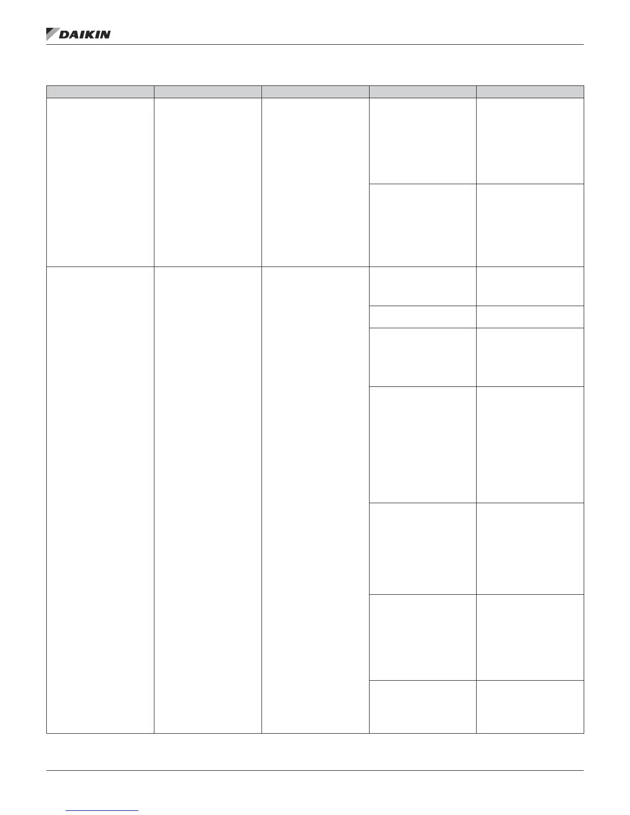
Table 25: Lockout Errors — DPS 003–015 only
Display Information Alert Description Possible Cause Solution
888
Ignition Board Failure
Ignition board start-up
checks have detected an
error.
A. Faulty transformer
1. Check 24-volt
transformer for correct
output.
2. Check connections and
wiring to control board
and other components
connected to the 24
volt source.
3. Replace if necessary.
B. Faulty control board
1. Turn off power to
the furnace, wait 30
seconds and turn
power back on. Re-try
ignition sequence
and see if the system
responds.
2. Replace control board if
necessary.
EO1
Failed Ignition
Maximum Retries
Exceeded
The ame could not be
established during multiple
trial-for-ignition periods.
The maximum number of
retries has been exceeded
and the furnace is in a
lock-out condition.
A. Insufcient gas line
pressure
1. Insure gas supply is
connected to furnace
and check for proper
line pressure.
B. Gas valve control turned
“OFF”
1. Turn gas valve to the
“ON” position.
C. No spark from direct
spark ignition
1. Check ignition voltage
(115 VAC from board to
transformer) and wiring.
2. Check 24 VAC
transformer for DSI
board.
D. Insufcient intermediate
gas manifold pressure
through gas safety
valve
1. Check for faulty gas
valve wiring.
2. Check 24 VAC to gas
valve assembly.
3. Check inlet pressure to
safety gas valve.
4. Check outlet pressure
from the safety gas
valve – adjust as
needed.
5. Replace safety gas
valve if faulty.
E. Insufcient gas manifold
pressure to burner
through modulating ball
valve assembly
1. Check voltage to gas
valve actuator. (7 – 10
VDC depending on
model)
2. Check alignment and
set screw connection
between ball valve
and actuator (See
Modulating Gas Valve
Alignment procedure).
F. Burners do not light
1. Check spark rod
assembly for proper
location, spark gap, etc.
2. Check for proper
mounting of the burner
assembly.
3. Check burner orice
for proper size and
blockage.
G. Burners light and
remain lit for about 5
seconds
1. Check ame rod wiring
and connections.
2. Check for proper
alignment of ame rod.
3. Clean ame rod sensor.
opTIonal gas heaT
www.DaikinApplied.com 57 IM 1125-7 • REBEL ROOFTOPS