EasyManua.ls Logo

Daikin DX14XA Series - User Manual

Daikin DX14XA Series
12 pages
Print Icon
To Next Page IconTo Next Page
Loading...
INSTALLATION INSTRUCTIONS
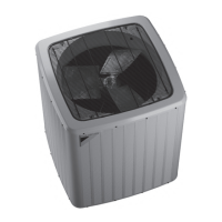
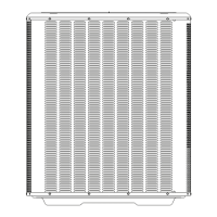
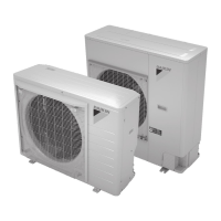
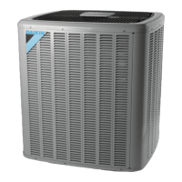
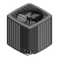
DX14XA SERIES
CONDENSING UNIT


IOD-1057A
09/2022

© 2022

www.daikincomfort.com
Important Safety Instructions























WARNING
WARNING
HIGH VOLTAGE




WARNING

Shipping Inspection






accept claims from dealers for transportation damage or

Codes & Regulations
This product is designed and manufactured to comply









 for Daikin

residential or commercial products menu and then select




The United States Environmental Protection Agency


follow these regulations may harm the environment


󰀩

must

NOTE: Installation of unmatched systems is strongly


NOTE:



Other manuals for Daikin DX14XA Series

Questions and Answers

Summary

Important Safety Instructions

General Service Personnel Training

Only trained personnel should service the equipment. Improper service can lead to injury or damage.

High Voltage Warning

Disconnect all power before servicing to avoid property damage, personal injury, or death.

Bypass Safety Devices Warning

Warning against bypassing safety devices to prevent potential hazards.

Installation Clearances

Outdoor Unit Placement

Consider structures, obstructions, and other units for proper air circulation. Maintain minimum 60 inches clearance.

Corner Installations

Corner installations are strongly discouraged due to potential service access issues.

Safe Refrigerant Handling

Refrigerant Hazards

Refrigerants are heavier than air and can displace oxygen. Handle in ventilated areas and wear protective gear.

Cylinder Safety

Never apply flame to cylinders. Store in cool, dry places. Do not overfill or mix refrigerants.

Refrigerant Line Connections

Brazing Precautions

Protect service valves from overheating with wet rags or heat trap compound. Use 2% minimum silver alloy.

Leak Testing

Use dry nitrogen and soapy water. Never use oxygen or flammable gases for leak testing.

Electrical Connections

Voltage Supply Requirements

Unit is designed for three-phase operation. Verify supply voltage matches unit rating plate requirements.

Wire Sizing and Voltage Drop

Size wires to limit voltage drop to 2% (max.) from main breaker. Consult NEC/CEC and local codes.

Phase Rotation and Connections

Three Phase Compressor Rotation

Verify rotation by checking suction pressure drop and discharge pressure rise. Switch leads if reversed.

Low Voltage Wiring

Use minimum 18 AWG wire for control wiring. Field connections must be made inside the control box.

System Operation and Adjustment

System Start Up

Never operate the compressor with the suction valve closed. Allow pressures to stabilize after startup.

Charge Verification and Adjustment

Check subcooling and superheat at outdoor temperatures above 60°F. Adjust charge for optimal performance.

Troubleshooting Basics

Check coils, filters, and airflow first. Indoor airflow should be 375-425 CFM per ton.

Overview

This document provides installation and service instructions for the Daikin DX14XA Series Condensing Unit, an air conditioning component. It emphasizes safety, proper installation procedures, and maintenance guidelines to ensure optimal performance and longevity of the equipment.

Function Description

The Daikin DX14XA Series Condensing Unit is an outdoor component of a split-system air conditioning system. Its primary function is to reject heat from the refrigerant, which has absorbed heat from the indoor space, to the outside air. This process is crucial for cooling the indoor environment. The unit is designed for outdoor installations only and is approved for operation above 55°F in cooling mode. Operation below 55°F requires an approved low ambient kit.

Important Technical Specifications

The manual highlights several critical technical specifications and requirements:

  • Voltage: The unit is designed for three-phase operation. It is crucial not to operate it on a single-phase power supply. The supply voltage must match the unit's rating plate power requirements.
  • Refrigerant: The unit uses R-410A refrigerant. Specific instructions are provided for handling R-410A, including warnings against purging into enclosed spaces, contact with liquid refrigerant, and burning refrigerant. Only returnable (not disposable) service cylinders should be used for refrigerant removal.
  • Starting Charge: For 7-1/2 ton units, the starting charge is 18 lbs of R-410A. For 10 ton units, it is 20 lbs. The unit ships with a holding charge of 55 oz.
  • Line Set Sizing: A table provides recommended refrigerant line lengths and diameters (Suction and Liquid Line OD) for different tonnage units (7-1/2 and 10 tons) across various length ranges (0-24 ft, 25-49 ft, 50-74 ft). For lines longer than 74 feet or with vertical elevation changes over 50 feet, reference to the TP-108* Long Line Set Application Guideline is advised.
  • Electrical Wiring: Wires should be sized to limit voltage drop to a maximum of 2% from the main breaker or fuse panel to the condensing unit. The wire size must be sufficient to carry the Minimum Circuit Ampacity (MCA) listed on the serial plate. The manual includes a table for maximum allowable length in feet to limit voltage drop to 2% for various wire sizes (AWG) and MCAs.
  • Voltage Unbalance: Supply voltage can be unbalanced (phase to phase) within 2%. A formula is provided to calculate the percentage of voltage unbalance.
  • Thermostat: The unit must be used with a purchased two-stage room thermostat with 24 VAC control circuitry.
  • Overcurrent Protection: Approved devices include time delay fuses and HACR type circuit breakers.

Usage Features

  • Installation Clearances: The top of the unit should be completely unobstructed. If vertical obstructions are present, a minimum of 60 inches between the top of the unit and the obstruction(s) is required. Corner installations are strongly discouraged.
  • Rooftop Installations: If installed on a roof, the structure must support the weight, and consideration should be given to weather-tight integrity and sound vibration transmission. Vibration-absorbing pads or springs can reduce noise.
  • Snow Accumulation Areas: In areas with heavy snow, the unit should be elevated above the average yearly snow accumulation to allow unobstructed drainage of defrost water and air flow. A minimum 3" clearance under the outdoor coil is required in milder climates.
  • Foundation: The unit must be placed on a solid, level foundation, preferably a concrete slab raised above ground level, minimum 6" wider than the unit in all directions. The foundation slab should not be in contact with or be an integral part of the building foundation to reduce sound transmission.
  • Refrigerant Line Installation: Use only refrigerant-grade copper tubing. Tubing should be cut square, deburred, and kept clean and dry. Avoid direct contact with plumbing, ductwork, or building structures. Use sound and vibration-absorbing material where lines pass through foundations or walls. Insulate the suction line with Armflex (or equivalent) with a minimum 1/2" wall thickness to prevent condensation.
  • Filter Drier and Sight Glass: A factory-installed liquid line filter drier is present. A field-supplied sight glass/moisture indicator should be installed on the liquid line as close as practical to the service valve.
  • Burying Refrigerant Lines: If lines must be buried, they should be insulated separately, enclosed in waterproof material (conduit or pipe) with sealed ends, and adequately protected if passing under or through a concrete slab.
  • Brazing: Use a brazing alloy with a minimum of 2% silver content. Wrap components like service valves, TXV valves, or filter driers with a wet rag or thermal heat trap compound during brazing to prevent overheating. "Sweep" the refrigerant line with nitrogen or inert gas during brazing to prevent copper-oxide formation.
  • Leak Testing: Use dry nitrogen and soapy water to locate leaks. Alternatively, charge with 10 psi refrigerant before using nitrogen to reach working pressure for leak detector use. Never use oxygen, high-pressure air, or flammable gases.
  • System Evacuation: Evacuate the system to 250 microns or less using both suction and liquid service valves. Hold vacuum for 10 minutes.
  • Three-Phase Compressor Rotation: For three-phase scroll compressors, verify proper rotation by observing suction pressure drop and discharge pressure rise when the compressor is energized. Incorrect rotation (reverse operation) results in noisier operation and substantially reduced current draw. To correct, switch any two leads at the unit contactor.
  • Low Voltage Connections: Use 18 AWG or larger wire. Field connections should be made inside the control box with solder-less connectors (wire nuts).
  • Charge Adjustment: After system stabilization, check subcooling (9°F to 13°F) and superheat. Adjust charge by adding or removing refrigerant slowly.

Maintenance Features

  • Troubleshooting: The manual provides a troubleshooting analysis table that links common complaints (e.g., High Pressure, Low Pressure, Low Suction Pressure, High Suction Pressure, Compressor will not start) to probable causes and recommended remedies.
  • General Maintenance: The troubleshooting section emphasizes checking for clean coils, clean filters, and proper airflow as a first step. Indoor airflow should be 375 to 425 CFM per ton of cooling.
  • Warranty: Damage to the unit caused by operating it in an incomplete structure or with the suction valve closed is not covered under warranty. Using used refrigerant not certified to AHRI standards may also cause compressor damage.

The document stresses the importance of adhering to national and local codes and regulations, including those from the United States Environmental Protection Agency (EPA) regarding refrigerants. It also advises against installing unmatched systems (condensing unit and air handler) and recommends consulting the unit Specification Sheet for indoor model selection.

Daikin DX14XA Series Specifications

General IconGeneral
BrandDaikin
ModelDX14XA Series
CategoryHeat Pump
LanguageEnglish

Related product manuals