INSTALLATION INSTRUCTIONS
HEAT PUMP
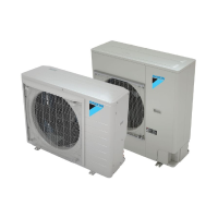
DZ17VSA HEAT PUMP
INSTALLATION & SERVICE REFERENCE
Index
Important Safety InStructIonS ............................................. 1
ShIppIng InSpectIon .............................................................. 2
codeS & regulatIonS .......................................................... 2
featureS.............................................................................. 2
acceSSorIeS ........................................................................ 2
Before InStallatIon .............................................................2
precautIonS for SelectIng a locatIon ................................. 3
precautIonS for InStallatIon ............................................... 3
InStallatIon clearanceS ......................................................4
cold clImate heat pump operatIon locatIon ...................... 5
rooftop InStallatIonS .........................................................5
electrIcal noISe ................................................................. 5
Safety conSIderatIonS......................................................... 6
meanIngS of SymBolS .......................................................... 6
refrIgerant lIneS ............................................................... 8
refrIgerant lIne connectIonS ........................................... 10
leak teStIng (nItrogen or nItrogen-traced) .................... 10
Stop ValVe operatIon method ........................................... 11
SyStem Start-up procedure .............................................. 11
Start-up procedure detaIl ................................................ 12
electrIcal connectIonS ....................................................12
Step 1. calculate refrIgerant charge BaSed on
lIne Set length .......................................................... 16
Step 2. connect heat pump to SyStem .............................. 18
Step 3. SyStem Start-up teSt ............................................ 18
addItIonal charge adjuStIng procedure .......................... 18
Step 4. adjuSt refrIgerant leVel ..................................... 18
Step 5. meaSure SuBcoolIng to VerIfy proper charge ..... 18
heat pump wIth outdoor temperature lockoutS ............... 19
wIrIng dIagram ................................................................ 20
teStIng capacItor reSIStance ............................................22
coolIng analySIS chart .................................................... 24
heatIng analySIS chart ..................................................... 25
trouBleShootIng ...............................................................26
SettIng the mode dISplay .................................................. 31
7-Segment dISplay ............................................................. 37
heat pump homeowner’S routIne maIntenance
recommendatIonS ........................................................ 40
Start up checklISt ........................................................... 41
ctk04 addendum ............................................................... 43
Important Safety InStructIonS
The following symbols and labels are used throughout this
manual to indicate immediate or potential safety hazards. It is
the owner’s and installer’s responsibility to read and comply
with all safety information and instructions accompanying
these symbols. Failure to heed safety information increases
the risk of personal injury, property damage, and/or product
damage. Also see “Meanings of Symbols” on page 6.
WARNING
HIGH VOLTAGE !
dISconnect all power Before SerVIcIng.
multIple power SourceS may Be preSent. faIlure
to do So may cauSe property damage, perSonal
Injury or death.
WARNING
only perSonnel that haVe Been traIned to InStall, adjuSt, Ser-
VIce or repaIr (hereInafter, “SerVIce”) the equIpment SpecIfIed
In thIS manual Should SerVIce the equIpment. the manufacturer
wIll not Be reSponSIBle for any Injury or property damage arIS-
Ing from Improper SerVIce or SerVIce procedureS. If you SerVIce
thIS unIt, you aSSume reSponSIBIlIty for any Injury or property
damage whIch may reSult. In addItIon, In jurISdIctIonS that re-
quIre one or more lIcenSeS to SerVIce the equIpment SpecIfIed In
thIS manual, only lIcenSed perSonnel Should SerVIce the equIp-
ment. Improper InStallatIon, adjuStment, SerVIcIng or repaIr of
the equIpment SpecIfIed In thIS manual, or attemptIng to InStall,
adjuSt, SerVIce or repaIr the equIpment SpecIfIed In thIS manual
wIthout proper traInIng may reSult In product damage, property
damage, perSonal Injury or death.
prop 65 warnIng
for calIfornIa conSumerS
WARNING
-
www.P65Warnings.ca.gov
CAUTION
do not waSh the heat pump wIth exceSSIVe water. an electrIc
Shock or fIre could reSult.
Our continuing commitment to quality products may mean a change in specications without notice.
© 2013, 2017-2019
Daikin Texas Technology Park,19001 Kermier Road,Waller, TX, 77484, U.S.A.
www.daikincomfort.com
3P515859-3P