EKMV2C09B7 + EKMV3C09B7
2-way valve kit/3-way valve kit for fan coil units
4PW65144-1B – 10.2011
Installation manual
4
Electrical connections
For the FWF
1 Install the KRP1B101 box and the EKRP1C11 PCB according to
the installation manual provided with the KRP1B101 kit.
For wiring of the EKRP1C11 PCB: see below.
For the FWC
1 Install the KRP1H98 box and the EKRP1C11 PCB according to
the installation manual provided with the KRP1H98 kit.
For wiring of the EKRP1C11 PCB: see below.
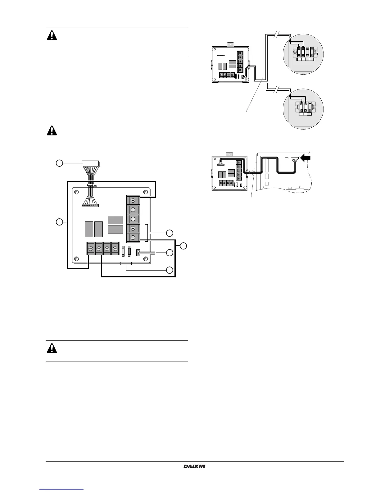
2 Wiring of the EKRP1C11
■ Power supply
■ Communication wire
Do not drill any holes in the casing of the unit to install the
option.
Only use the accessories provided by Daikin to install the
option.
The EKRP1C11 can only be used to connect the valves.
The functions mentioned in the installation manual of the
EKRP1C11 can not be used.
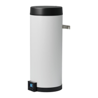
1 Communication to fan coil PCB
2 Power supply wire (to fan coil unit)
3 Fuses 5 A - 250 V
4 YC-Y1: connection of first valve
5 X1-Y4: wire to enable the use of the second valve (supplied
with valve kit)
6 X2-YC: connection of second valve
Do not bundle low and high voltage wires together. Bundle
all wires with the included clamps in order to avoid contact
with fan coil PCB’s or sharp edges.
X1 X2 X3 X4
CN1
Y4
Y3
Y2
Y1
YC
CN2
4
1
5
2
6
3
F1U F2U