ESIE11-02 Pre-Test Run Checks
Part 4 – Commissioning and Test Run 4–23
3
4
5
1
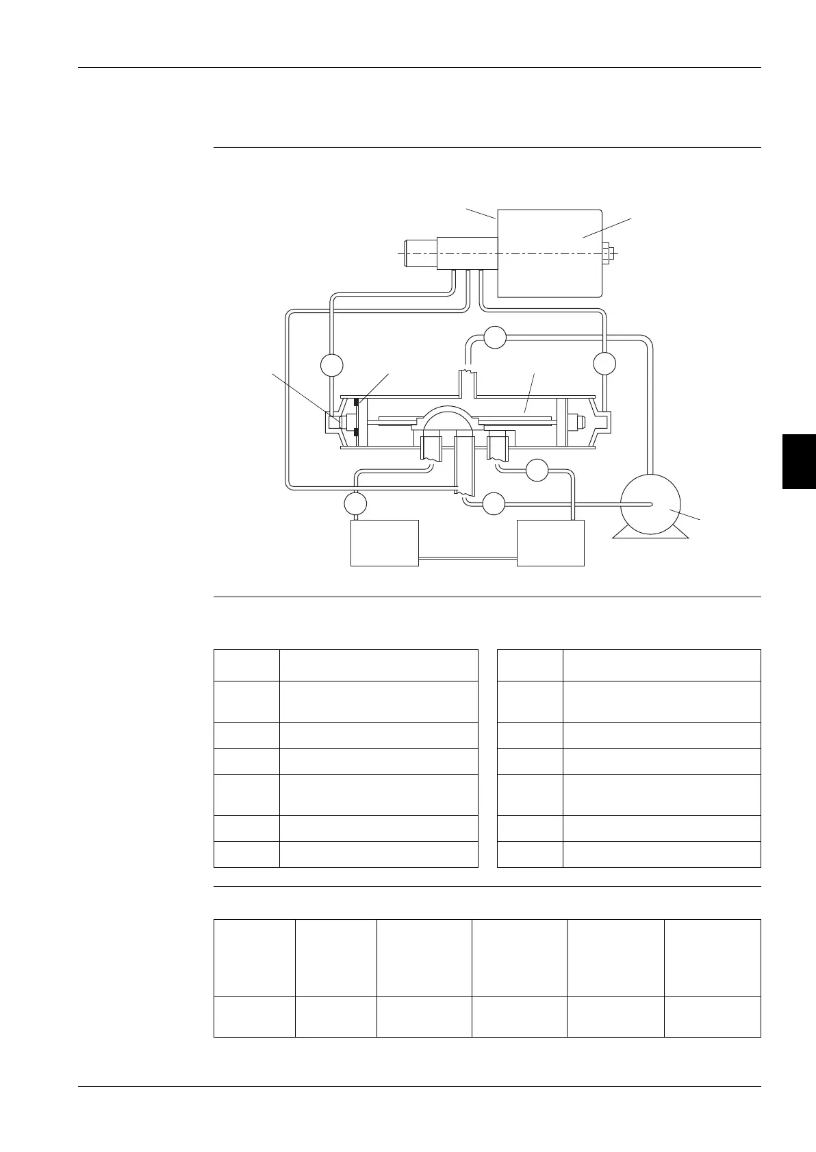
1.12 Control of the function of the 4-way valve for EUWY*5-24KBZW1
Illustration The illustration below shows the main components of the 4-way valve and of the connections with the
4-way valve.
Components The table below lists the main components of the 4-way valve and of the connections with the 4-way
valve.
Normal cooling The table below contains the normal condition of the 4-way valve in cooling mode.
5
1
6
4
23
Symbol Description Symbol Description
1 Discharge tube from the
compressor
a Pilot body
2 Suction tube to the compressor b Coil
3 Tube to the plate heat exchanger c Piston body
4 Tube to the air-cooled heat
exchanger
d Compressor
5 Left pilot back capillary tube e Piston needle
6 Right pilot back capillary tube f Bleed hole
Discharge
tube 1
Suction
tube 2
Tube to the
plate heat
exchanger
Tube to the
air-cooled
heat
exchanger
Left pilot
back capil-
lary tube
Right pilot
back capil-
lary tube
Hot Cool Cool as in
column 2
Hot as in
column 1
Temperature
of valve body
Temperature
of valve body
 Loading...