6 Configuration
Installation manual
10
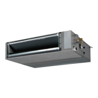
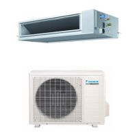
FBA35~140A2VEB
Split system air conditioners
4P456962-1C – 2017.04
▪ Master unit: Be sure to connect the wiring when combining with a
simultaneously operating multi-type in group control.
▪ Use separate power only in case of following combination:
1×FBA35A + RXS35L or RXM35M
2×FBA60A + RR100/125B or RQ100/125B
2×FBA71A + RR100/125B or RQ100/125B
4×FBA50A + RZQ200C
3×FBA60A + RZQ200C
3×FBA71A + RZQ200C
2×FBA100A + RZQ200C
4×FBA60A + RZQ200C
2×FBA125A + RZQ200C
▪ EN/IEC 61000‑3‑12 provided that the short-circuit power S
sc
is
greater than or equal to the minimum S
sc
value at the interface
point between the user's supply and the public system.
▪ EN/IEC 61000‑3‑12 = European/International Technical
Standard setting the limits for harmonic currents produced by
equipment connected to public low-voltage systems with input
current >16A and ≤75A per phase.
▪ It is the responsibility of the installer or user of the equipment to
ensure, by consultation with the distribution network operator if
necessary, that the equipment is connected only to a supply
with a short-circuit power S
sc
greater than or equal to the
minimum S
sc
value.
▪ Ensure that equipment is connected only to a supply with a short-
circuit power S
sc
greater than or equal to S
sc
in table below.
Combination FBA35A FBA50A FBA60A FBA71A
RZAG71M 2 (—) — — 1 (—)
RZQG71L
RZAG100M 3 (2.31) 2 (1.30) — —
RZQG100L
RZAG125M 4 (3.33) 3 (2.32) 2 (2.05) —
RZQG125L
RZAG140M 4 (3.33) 3 (2.32) — 2 (2.05)
RZQG140L
RZASG71M 2 (1.10) — — 1 (1.22)
RZQSG71L
RZASG100M 2 (1.65) 2 (—) — —
RZQSG100L
RZASG125M 4 (3.33) 3 (2.32) 2 (2.05) —
RZQSG125L
RZASG140M 4 (3.33) 3 (2.32) — 2 (2.05)
RZQSG140L
Combination FBA100A FBA125A FBA140A
RZAG71M — — —
RZQG71L
RZAG100M 1 (0.73) — —
RZQG100L
RZAG125M — 1 (0.74) —
RZQG125L
RZAG140M — — 1 (0.74)
RZQG140L
RZASG71M — — —
RZQSG71L
RZASG100M 1 (—) — —
RZQSG100L
RZASG125M — 1 (0.74) —
RZQSG125L
RZASG140M — — 1 (0.74)
RZQSG140L
INFORMATION
In case of group control it is not necessary to address the
indoor unit. The address is automatically set when the
power is activated.
6 Configuration
6.1 Field settings
Make the following field settings so that they correspond with the
actual installation setup and with the needs of the user:
▪ External static pressure setting using:
▪ Airflow automatic adjustment setting
▪ User interface
▪ Time to clean air filter
To set airflow automatic adjustment
▪ When the air conditioning unit is running in fan operation mode:
1 Stop the air conditioning unit.
2 Set second code number to 03.
Setting content: Then
2
M C1 C2
Airflow adjustment is OFF 11(21) 7 01
Press ON/OFF to return to normal operating
mode.
Possible consequence: The operation lamp
will light up and the unit will start the fan
operation for airflow automatic adjustment.
03
Operation stops after 1 to 8 minutes.
Possible consequence: Setting is finished
and the operation lamp will be off.
02
If there is no change after airflow adjustment, perform the setting
again.
User interface
Check the indoor unit setting: the second code number of mode
11(21) must be set to 01.
(2)
Field settings are defined as follows:
▪ M: Mode number – First number: for group of units – Number between brackets: for individual unit
▪ C1: First code number
▪ C2: Second code number
▪ : Default
 Loading...