T
Tara HendersonAug 8, 2025
What to do if Daikin FBQ100D2VEB detects multiple master units?
- CCynthia BeardAug 8, 2025
If your Daikin Air Conditioner detects multiple master units, connect the remote controller to only one indoor unit.
What to do if Daikin FBQ100D2VEB detects multiple master units?
If your Daikin Air Conditioner detects multiple master units, connect the remote controller to only one indoor unit.
What to do if Daikin FBQ100D2VEB Air Conditioner has gas shortage due to clogging in refrigerant piping?
If you suspect clogging in the refrigerant piping system of your Daikin Air Conditioner, check for a failure to open the stop valve and any clogging within the refrigerant system.
What does excess indoor units connected error mean on Daikin Air Conditioner?
This error will be displayed if five or more indoor units are connected to your Daikin Air Conditioner.
Why does my Daikin Heat Pump emit an odor?
If your Daikin Heat Pump emits an odor, it's likely due to room smells and cigarette odors that have accumulated inside the indoor unit. To resolve this, the inside of the indoor unit must be cleaned.
Lists model names for various indoor/outdoor unit combinations and their compatibility.
Visual guide showing the appearance of different outdoor units for identification.
Displays cooling and heating operating temperature ranges for different models.
Details applicable models, names, and functions of wired controllers for operation.
Covers applicable models, names, and functions of wireless controllers for operation.
Explains how to access and use service modes for maintenance and diagnosis.
Describes how to use inspection mode for checking unit status and error codes.
Details the roles of key components and thermistors in system operation.
Illustrates the operational logic for cooling, dry, and heating modes.
Provides in-depth explanations of indoor and outdoor unit operational functions.
Outlines the procedure and precautions for initial unit testing after installation.
Guides on configuring settings using wired and wireless remote controllers.
Explains how to adjust settings using DIP switches and BS buttons on the PCB.
Details methods for operating the unit in emergency situations.
Lists essential inspections for routine maintenance and system health.
Provides troubleshooting steps based on observed operational symptoms.
Helps diagnose issues using LED indicators on indoor and outdoor units.
Guides on diagnosing errors and warnings displayed on the remote controller.
Visual representation of the refrigerant piping system for specific models.
Electrical schematics for outdoor units, detailing component connections.
Provides thermodynamic data for the R-410A refrigerant.
Step-by-step instructions for safely removing and mounting the switchbox.
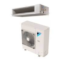
| Cooling Capacity | 10.0 kW |
|---|---|
| Heating Capacity | 11.2 kW |
| Refrigerant | R410A |
| Power Supply | 220-240 V, 50 Hz |
| Air Flow (Indoor Unit) | 1800 m3/h |