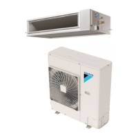
• Indoor Units • R-410A • FBQ-B8V1_FBQ-B8V3B
1
6
• Split Sky Air • Indoor Units
11
6 Dimensional drawing & centre of gravity
6 - 1 Dimensional drawing
3TW22224-1C
FBQ35-50B
view A
750 (Suspension position)
view B
Notes:
1. Refer to ’outlook drawing for installing optional accessories’ when installing
optional accessories.
2. The required ceiling depth varies according to configuration of the specific system.
3. For maintenance of the air filter, it is necessary to provide a service access panel
according to the installation method. (Refer to the ’filter installation method’
drawing)
1
Liquid pipe connection J A Flare connection
2 Gas pipe connectionJ B Flare connection
3 Drain pipe connection VP25 (I.D. J 32, I.D. J 25)
4 Remote control wiring connection
5 Power supply connection
6 Drain hole VP25 (I.D. J 32, I.D. J 25)
7 Air filter
8 Air suction side
9 Air discharge side
10 Name plate
Suspension bolt
350 or more
(Installation space)
(Knock out hole)
300mmormore
(Service space)
view C
Fresh air intake position
(On circumference)
595 (Air suction panel center)
Model A B
FBQ35 6.35 9.52
FBQ50 6.35 12.70
3TW22244-1D
FBQ60-71B
view A
1050 (Suspension position)
view B
Notes:
1. Refer to ’outlook drawing for installing optional accessories’ when installing
optional accessories.
2. The required ceiling depth varies according to configuration of the specific system.
3. For maintenance of the air filter, it is necessary to provide a service access panel
according to the installation method. (Refer to the ’filter installation method’
drawing)
1
Liquid pipe connection J A Flare connection
2 Gas pipe connectionJ B Flare connection
3 Drain pipe connection VP25 (I.D. J 32, I.D. J 25)
4 Remote control wiring connection
5 Power supply connection
6 Drain hole VP25 (I.D. J 32, I.D. J 25)
7 Air filter
8 Air suction side
9 Air discharge side
10 Name plate
Suspension bolt
350 or more
(Installation space)
(Knock out hole)
500 mm or more
(Service space)
view C
Fresh air intake position
(On circumference)
595 (Air suction panel center)
Model A B
FBQ60 6.35 12.70
FBQ71 9.52 15.90
630 (Suspension
position)

 Loading...


