22English
(2) Turn the main/sub changeover switch on one of the two remote controller PC boards to “S”. (Leave the
switch of the other remote controller set to “M”.) (Refer to Fig. 13)
Wiring Method (See “9. ELECTRIC WIRING WORK’’.)
(3) Remove the control box lid
(4) Add remote controller 2 (slave) to the terminal block for remote controller (P
1
, P
2
) in the control
box. (There is no polarity.)
11. FIELD SETTING
NOTE
• Before 12. TEST OPERATION, be sure to make the following field settings as explained in 11. FIELD
SETTING.
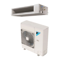
• Be sure to check that the outdoor unit has been wired.
• Make sure the control box lids are closed on the indoor and outdoor units.
• Field setting must be made from the remote controller in accordance with the installation condition.
• Setting can be made by changing the “MODE NO.”, “FIRST CODE NO.”, and “SECOND CODE NO.”.
• For setting and operation, refer to the “FIELD SETTING” in the installation manual of the remote controller.
• Do not set numbers unless mentioned in the table.
S
M
S
S
M
Remote
controller
PC board
(Factory setting)
(Only one remote
controller needs
to be changed if
factory settings
have remained
untouched.)
Fig. 13
P1 P2
Remote
controller 1
(Master)
Remote
controller 2
(Slave)
Terminal for remote
controller wiring
Outdoor unit
Remote
controller 1
Remote
controller 2
Fig. 14
01_EN_3PN06583-10W.fm Page 21 Thursday, March 24, 2011 9:03 AM
 Loading...