6 Installation
Installer and user reference guide
18
FCAG35~140AVEB
Split system air conditioners
4P473927-1 – 2017.03
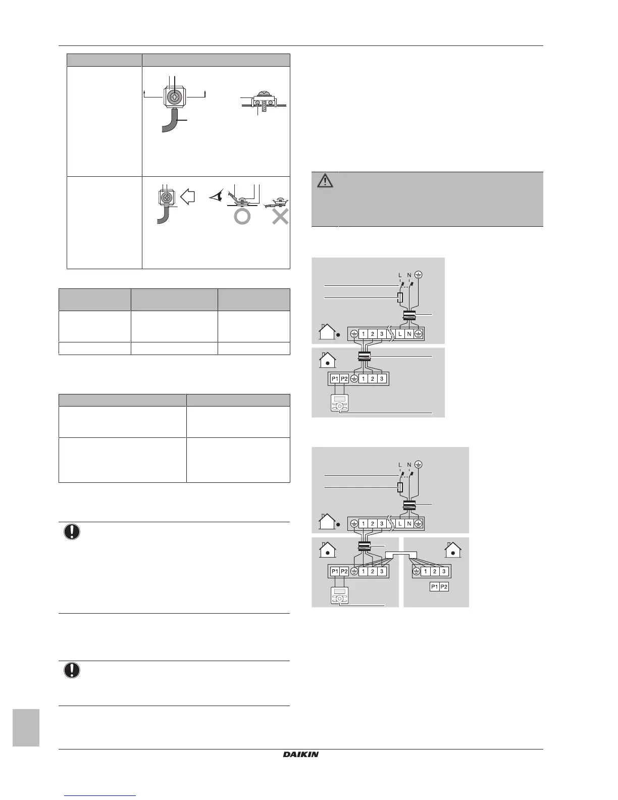
Wire type Installation method
Single core wire
a Curled single core wire
b Screw
c Flat washer
Stranded conductor
wire with round
crimp-style terminal
a Terminal
b Screw
c Flat washer
Tightening torques
Wiring Screw size Tightening torque
(N•m)
Interconnection
cable
(indoor↔outdoor)
M4 1.18~1.44
User interface cable M3.5 0.79~0.97
6.4.4 Specifications of standard wiring
components
Component Specification
Interconnection cable
(indoor↔outdoor)
Minimum cable section of
2.5mm² and applicable for
230V
User interface cable Vinyl cords with 0.75 to
1.25mm² sheath or cables
(2‑core wires)
Maximum 500m
6.4.5 To connect the electrical wiring on the
indoor unit
NOTICE
▪ Follow the wiring diagram (delivered with the unit,
located at the inside of the service cover).
▪ For instructions on how to connect the decoration panel
and the sensor kit, see the installation manual delivered
with the panel or the kit.
▪ Make sure the electrical wiring does NOT obstruct
proper reattachment of the service cover.
It is important to keep the power supply and the transmission wiring
separated from each other. In order to avoid any electrical
interference the distance between both wiring should always be at
least 50mm.
NOTICE
Be sure to keep the power line and transmission line apart
from each other. Transmission wiring and power supply
wiring may cross, but may not run parallel.
1 Remove the service cover.
2 User interface cable: Route the cable through the frame,
connect the cable to the terminal block, and fix the cable with a
cable tie.
3 Interconnection cable (indoor↔outdoor): Route the cable
through the frame, connect the cable to the terminal block
(make sure the numbers match with the numbers on the
outdoor unit, and connect the earth wire), and fix the cable with
a cable tie.
4 Divide the small sealing (accessory) and wrap it around the
cables to prevent water from entering the unit. Seal all gaps to
prevent small animals from entering the system.
WARNING
Provide adequate measures to prevent that the unit can be
used as a shelter by small animals. Small animals that
make contact with electrical parts can cause malfunctions,
smoke or fire.
5 Reattach the service cover.
▪ Pair type or multi-system. 1 user interface controls 1 indoor unit.
▪ Simultaneous operation system. 1 user interface controls 2
indoor units (indoor units operate simultaneously)
▪ Group control. 1 user interface controls up to 16 indoor units (all
indoor units operate according to the user interface).