Do you have a question about the Daikin FDMR36ERV16 and is the answer not in the manual?
Crucial safety warnings for installation and maintenance, covering electrical hazards, grounding, and wiring precautions.
Important installation cautions regarding flammable gas, drainage, sharp edges, and environmental factors.
Specific information regarding refrigerants, emphasizing clean, dry, and tightly sealed systems for R410A/R22.
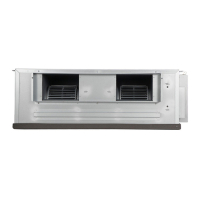
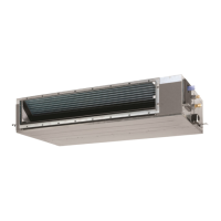
Instructions for securely mounting indoor units, ensuring proper support, alignment, and levelness for optimal operation.
Detailed steps for installing drain piping to prevent leaks and condensation, including slope and insulation requirements.
Guidelines for selecting the optimal location for outdoor units to ensure proper airflow, ventilation, and protection from environmental factors.
Guidelines on maximum refrigerant pipe length and number of bends to maintain system capacity and prevent compressor failure.
Details the recommended liquid and gas pipe sizes for connecting indoor and outdoor units for various Daikin models.
Specific instructions for correctly mounting the TXV bulb on the suction line for accurate temperature sensing.
Proper procedures for brazing copper tubing, including using nitrogen gas and removing burrs to ensure system integrity.
Guidelines for connecting flare nuts using a torque wrench, specifying torque values for different pipe sizes.
Steps for verifying unit mounting, leak-proofing, wiring, and conducting a test run to ensure proper operational status.
Detailed steps for vacuuming the refrigeration circuit to remove moisture and air, ensuring proper system integrity.
Instructions for charging the system with the correct refrigerant amount, including precautions and guidelines.
Provides a table of recommended refrigerant charge amounts for various indoor and outdoor unit combinations.
Table detailing the additional refrigerant charge required per meter of liquid pipe length for longer applications.
Guidelines for refilling compressor oil in case of spill or loss, based on indoor/outdoor unit combinations and pipe length.
Graph illustrating standard operating conditions for cooling, including outdoor and indoor temperature ranges and piping length.
Explanation of the auto random re-start function, which resumes operation after a power interruption.
Procedure for cleaning and maintaining the indoor air filter, including frequency and recommended cleaning agents.
Instructions for cleaning the indoor unit's grille and panel, specifying cleaning agents and frequency.
Addresses issues like compressor not operating, low airflow, bad odor, and condensation with causes and actions.
Explains common error codes displayed on the remote, such as HP, LP, SPPR, AF, C-Er, and df1, with their causes and solutions.
Explains how to adjust temperature, select operating modes (Cool/Fan), and set fan speeds using the controller.
Details functions accessible via Menu Mode: Key Pad Lock, Clock Setting, Filter Reset, and Factory Reset.
Guide to setting daily and weekly timers for the air conditioning unit, including ON and OFF times.
Instructions for activating the Energy Saver mode and basic ON/OFF operation of the unit.
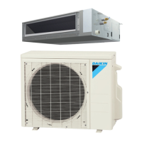
This document serves as an installation and operation manual for Daikin ceiling-concealed split-type air conditioners. It provides comprehensive guidelines to ensure safe, efficient, and proper functioning of the appliance. The manual is intended for use by expert and trained users in various settings, including shops, light industry, farms, and commercial environments.
The manual emphasizes critical safety precautions for both installation and maintenance. It highlights that all installation and maintenance tasks must be performed by qualified personnel familiar with local codes and regulations. Proper electrical wiring, in accordance with national wiring regulations, is paramount, and the unit must be grounded to prevent electrical hazards. The importance of installing an earth leakage breaker is stressed to prevent electric shocks or fire.
Users are warned against touching refrigerant piping or moving fan parts with electrical wiring. Before any servicing or installation, the unit must be switched off and disconnected from the main power supply. Pulling the power cord while the unit is on is strictly prohibited due to the risk of electric shocks and fire. To prevent interference, indoor and outdoor units, power cables, and transmission wiring should be kept at least 1 meter away from TVs and radios.
Several cautions are also provided:
The system uses R410A/R22 refrigerant, requiring strict precautions to keep the system clean, dry, and tightly sealed. Impurities, including SUNISO oil, other mineral oils, and moisture, must be kept out. The system must be kept tight during installation. R410A is a mixed refrigerant that does not contain chlorine, does not destroy the ozone layer, and contributes only slightly to the greenhouse effect if released. Additional R410A refrigerant must be charged in its liquid state; charging in gaseous state can lead to composition changes and abnormal system function. The design pressure of the system is 4.17MPa.
The indoor unit must be mounted on strong overhead supports, ensuring it can bear the unit's weight. Hanger rods should be aligned and securely fastened, and the fan-coil unit's base must be level in both horizontal directions, accounting for the recommended gradient for drainage flow. Clearances for servicing and optimal airflow are specified, and the unit should be positioned to prevent short-circuiting of cool discharge air. Direct sunlight on the unit should be avoided, and the location should be suitable for piping and drainage, with ample distance from doors.
During brazing of liquid and gas pipes for the indoor unit, a wet cloth should be used to prevent insulation burning, and insulation must be applied after brazing. M10/M12 rods should be used for installation, with the number of rods corresponding to the number of hanger metals provided.
Drain piping must be installed as shown in the diagram to prevent leaks and condensation. Piping should be as short as possible and slanted to improve flow, with the unit tilted between 10 to 15mm. The drain pipe slope should be at least 1:100. Secure insulation of the drain pipe is crucial. A drain trap must be provided at the drain outlet to relieve pressure differences between the unit and the outside atmosphere, preventing splashes or odors. Pipes should be kept straight for easy cleaning and to prevent dirt accumulation. A water drainage test must be conducted after installation to ensure smooth flow. In humid environments, an extra drain pan covering the entire indoor unit area is recommended.
The outdoor unit should be installed to prevent discharged air from being drawn back in (short-circuiting). Sufficient space for maintenance around the unit is required. The coolest possible location should be chosen, where intake air does not exceed 48°C. Obstructions to airflow must be removed. When multiple outdoor units are installed, they must be positioned to prevent one unit from drawing in the discharge air of another, whether side-by-side or stacked. All units should face the same or opposite directions to avoid short-circuiting. The location must be well-ventilated, capable of bearing the unit's weight, and isolating noise and vibration. Protection from direct sunlight (e.g., an awning) is advisable. Smooth drainage of rainwater and defrost water is necessary, and the unit should not be buried in snow or exposed to strong winds. The location should not annoy neighbors with air discharge or operating sound levels, and it should not be susceptible to dust or oil mist.
Operating the condensing unit in atmospheres containing oils (including machine oils), salt (coastal areas), or sulphide gas (near hot springs, oil refinery plants) can lead to unit failure.
Guidelines for installation clearance are provided for various outdoor unit models (RR36ERY16, RR65FRY16, R65DSY16, R60GRY16, RR100FRY16, R100DSY16, R90GRY16, RR130FRY16, R130DSY16, R120GRY16) to prevent hot air short-circuiting when multiple units are installed. Specific dimensions (A, B, C, D) are given for horizontal air discharge configurations.
A table lists compatible wired and optional wireless remote controllers for various indoor unit models. The wireless remote is optional and can be used with the IR sensor provided in the wired remote, which comes as an accessory with indoor units.
The manual details maximum pipe length and number of bends. Excessive pipe length or bends can reduce capacity and reliability, potentially leading to compressor failure. The shortest path is always recommended. Field piping arrangements require liquid loops or oil traps based on the relative positions of indoor and outdoor units. A field-supplied sight glass must be assembled and mounted as shown in the figure. The guarantee on performance is revoked if piping height, length, or number of bends exceed specified limits. Bends must be made carefully to avoid crushing the pipe, using a pipe bender.
A table provides specific liquid and gas pipe sizes for various indoor and outdoor unit models, along with the refrigerant type (R410A or R22). For FD130DSV16/FD120GRV16 and R130DSY16/R120GRY16, a reducer is needed at the indoor unit end for gas pipe connection.
Only the designated refrigerant should be used, and no other substances like air or nitrogen should mix into the cycle. Any refrigerant gas leaks during work require thorough room ventilation. The correct refrigerant type must be added as detailed in the table. Installation tools must be exclusively used for specific refrigerant types to withstand pressure and prevent foreign materials (e.g., mineral oils, moisture) from mixing into the system.
The TXV bulb should be clamped to the suction line near the evaporator outlet, preferably on a horizontal run. The suction line must be completely clean before clamping the bulb. The bulb should be clamped to a free-draining suction line and insulated from ambient temperature. After installation, the TXV bulb must be fixed at the 8 o'clock or 4 o'clock position on the suction line.
Contaminated or damaged copper tubing should not be used. If any piping, evaporator, or condenser has been exposed to air for more than 15 seconds, it must be vacuumed and purged with field-supplied refrigerant. Plastic, rubber plugs, and brass nuts should remain on valves, fittings, tubings, and coils until ready for connection. During brazing, nitrogen gas must be passed through the coil and joints to prevent soot formation inside copper tubings. Pipes should be cut stage by stage with a pipe cutter, advancing the blade slowly to avoid distortion and burrs. Burrs must be removed from cut edges, holding the pipe end downwards to prevent metal chips from entering.
The center of the piping should be aligned, and flare nuts tightened sufficiently by hand, then fully tightened with a torque wrench until it clicks. The tightening direction must follow the arrow indicated on the wrench. A table provides torque values for different pipe sizes.
Electrical connection values are for information only and must comply with local/national codes and regulations. The appropriate voltage range should be checked against the unit's data label. Specifications for power supply cable size, number of conductors, interconnection cable size, and recommended fuse amperage are provided for various indoor and outdoor unit models, including single-phase and three-phase systems. Wiring diagrams illustrate connections for different unit configurations.
After installation, a thorough check is required:
Vacuuming is essential to eliminate moisture and air from the system. The outdoor unit is equipped with valve fittings. Before vacuuming, a leak check of the refrigeration circuit must be performed. Flexible hoses should be connected to the charging nipples via standard servicing valves and pressure gauges. The system should be vacuumed to at least 500 microns Hg. The unit should not be started while vacuuming.
Before recharging, the vacuum must be held at 500 microns Hg for at least 15 minutes. Then, break the vacuum by charging the correct refrigerant type. The unit should operate for 15 minutes to ensure the refrigerant charge is correct. After confirming the charge, remove flexible hoses and replace caps.
Refrigerant should only be charged after field work, leak testing, and vacuum drying are complete. The maximum permissible charge must not be exceeded to avoid liquid hammer. Charging with unstable substances can cause explosions and accidents, so only appropriate refrigerant types should be used.
A table provides refrigerant charge levels (kg/7.5m pipe length) for various indoor and outdoor unit models in cooling-only operation. Specific notes are included for multi-unit systems, detailing additional charge requirements for standard pipe lengths. A minimum pipe length of 7.5m must be maintained during installation.
A table specifies additional refrigerant charge (kg/meter) based on liquid pipe size. This is a guideline for longer piping applications, and actual charge may vary based on application and site conditions.
In case of a major oil spill or loss due to leakage, all remaining oil must be removed from the compressor, and fresh oil charged according to the provided table. To remove oil, the compressor should be removed from the system, tilted to allow all oil to drain from the suction port. The quality of the oil (clear, not black or turbid) determines if the same oil can be used for refilling or if fresh oil is required. Oil should be charged through the suction port of the compressor.
These precautions apply to Scroll compressors using R22, R407C, R134A, R404A, R507, and R410A refrigerants. Scroll compressors have high volumetric efficiency and can quickly pump a deep vacuum if refrigerant is insufficient or added too slowly. Low suction pressure can lead to high discharge temperatures, causing poor lubrication and high friction between scroll flanks and tips, generating excessive heat. This can damage the Scroll spirals and orbiting Scroll bearing, potentially leading to failure within minutes or hours. Other charging problems like undercharging, overcharging, moisture, or air in the system can also cause compressor failure.
Minimal equipment is needed for field charging: service gauges, hoses, vacuum pump, vacuum gauge, scales, and thermometer. The proper refrigerant charge must follow manufacturer recommendations.
For single-phase compressors, the system should be evacuated to 500 microns Hg (67Pa) using short, large-diameter hoses connected to unrestricted service ports. A reliable vacuum gauge is essential. Liquid refrigerant should be charged through the liquid line charging port until flow stops or the correct charge is weighed in. If additional charge is needed, start the system and slowly bleed liquid into the suction side, carefully monitoring suction and discharge pressures to ensure suction pressure does not fall below 25 psig (1.7 bar). Various methods for controlled liquid charging into the suction side are listed.
For three-phase compressors, the procedure is similar, but if the compressor runs in the wrong direction on starting, any two phases must be reversed. Short-term reverse rotation will not damage the compressor. Scroll compressors have internal discharge temperature protectors that trip and lock out the compressor for 30 minutes if discharge temperatures become dangerously high. The module can be reset by breaking the power supply to the control circuit after the compressor cools down. Bypassing this protector can damage the compressor and lead to premature failure.
Caution is advised regarding refrigerant leaks: air conditioning facilities must be installed in a sufficiently large room to ensure that the maximum concentration level of refrigerant gas is not exceeded in the event of a major leak, in accordance with local regulations and standards.
A graph illustrates the continuous operation range based on indoor and outdoor temperatures (CDB). Notes specify the conditions for the graph: equivalent piping length of 7.5m, level difference of 0m, and high airflow rate.
If a power cut occurs during operation, the unit will automatically resume the same operating mode when power is restored (applicable only to units with this feature).
Maintenance procedures are outlined for indoor air filters and the indoor unit.
A troubleshooting guide lists common fault conditions, their causes, and recommended actions.
If any fault persists, the local dealer/serviceman should be contacted.
Units with Scroll Compressors can only rotate in one direction. A phase protector prevents incorrect wiring of electrical phases. If phases are not connected correctly, the protector activates, and the unit will not start. This device is located in the outdoor unit's control box. A table shows LED indicator lights (LED, RV, UV, OV, AS) for normal operation and various fault conditions (single phasing, phase reversal, unbalance, over voltage, under voltage), along with recommended actions (switch off unit, check wiring/voltage).
A diagram illustrates the SLM controller with numbered indications for various functions:
| Cooling Capacity | 3.6 kW |
|---|---|
| Heating Capacity | 4.0 kW |
| Refrigerant | R32 |
| Cooling Capacity (BTU/hr) | 12, 300 BTU/hr |
| Power Supply | 220-240 V, 50 Hz |
| Type | Wall Mounted |