2. WHAT TO DO BEFORE
OPERATION
Refer to the operation manual attached to the
indoor unit.
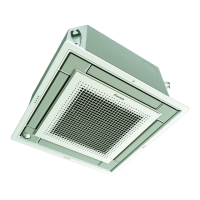
3. NAMES AND FUNCTIONS OF
THE OPERATING SECTION
(Refer to Fig. 1-1, 1-2, 2 on page
[1])
1
DISPLAY “
” (SIGNAL TRANSMISSION)
This blinks when a signal is being transmitted.
2
DISPLAY “
” “ ” “ ” “ ” “ ”
(OPERATION MODE)
This display shows the current OPERATION
MODE. Operation modes supported depend on
the model that is connected.
3
DISPLAY “NOT AVAILABLE” (displayed
when operation is not supported)
When a button for a function that is not
supported on the connected model is pressed,
this displays for 2 seconds.
4
DISPLAY “
” (SET TEMPERATURE)
This display shows the set temperature.
5
DISPLAY “
” (PROGRAMMED TIME)
This display shows PROGRAMMED TIME of
the air conditioner start or stop.
6
DISPLAY “
” (AIRFLOW BLADE)
Refer to page 8, 9.
7
DISPLAY “
” (FAN SPEED)
The display shows the set fan speed.
8
DISPLAY “
” (INSPECTION)
When the INSPECTION BUTTON is pressed,
the display shows the system mode is in.
Do not operate this button during normal use.
9
ON/OFF BUTTON
Press the button and the air conditioner
will start. Press the button again and the air
conditioner will stop.
10
FAN SPEED CONTROL BUTTON
Press this button to select the fan speed.
11
TEMPERATURE SETTING BUTTON
Use this button for SETTING TEMPERATURE.
12
BACKLIGHT BUTTON
Press this button to turn the backlight on or off.
13
SIGNAL TRANSMITTER
This sends the signals to the indoor unit.
14
PROGRAMMING TIMER BUTTON
Use this button for programming “START and/
or STOP” time.
15
TIMER MODE ON/OFF BUTTON
Refer to page 9.
16
TIMER RESERVE/CANCEL BUTTON
Refer to page 9.
17
AIRFLOW DIRECTION ADJUST BUTTON
Refer to page 8.
18
OPERATION MODE SELECTOR BUTTON
Press this button to select OPERATION MODE.
“
” (COOLING), “ ” (HEATING),
“
” (AUTOMATIC), “ ” (FAN),
“
” (PROGRAMME DRY).
19
FILTER SIGN RESET BUTTON
Refer to the section of MAINTENANCE in the
operation manual attached to the indoor unit.
20
INSPECTION BUTTON
Thisbuttonisusedonlybyqualiedservice
persons for maintenance purposes.
Do not operate this button during normal use.
21
EMERGENCY OPERATION SWITCH
This switch is readily used if the remote
controller does not work.
22
RECEIVER
This receives the signals from the remote
controller.
23
OPERATING INDICATOR LAMP (Red)
This lamp stays lit while the air conditioner runs.
Itasheswhentheairconditionerisintrouble.
24
TIMER INDICATOR LAMP (Green)
This lamp stays lit while the timer is set.
25
AIR FILTER CLEANING TIME INDICATOR
LAMP (Red)
Lightsupwhenitistimetocleantheairlter.
26
DEFROST OPERATION LAMP (Orange)
Lights up when the defrosting operation has
started.
3 English
02_EN_3P477582-1.indd 3 6/15/2017 15:17:39