16
Installation Guideline
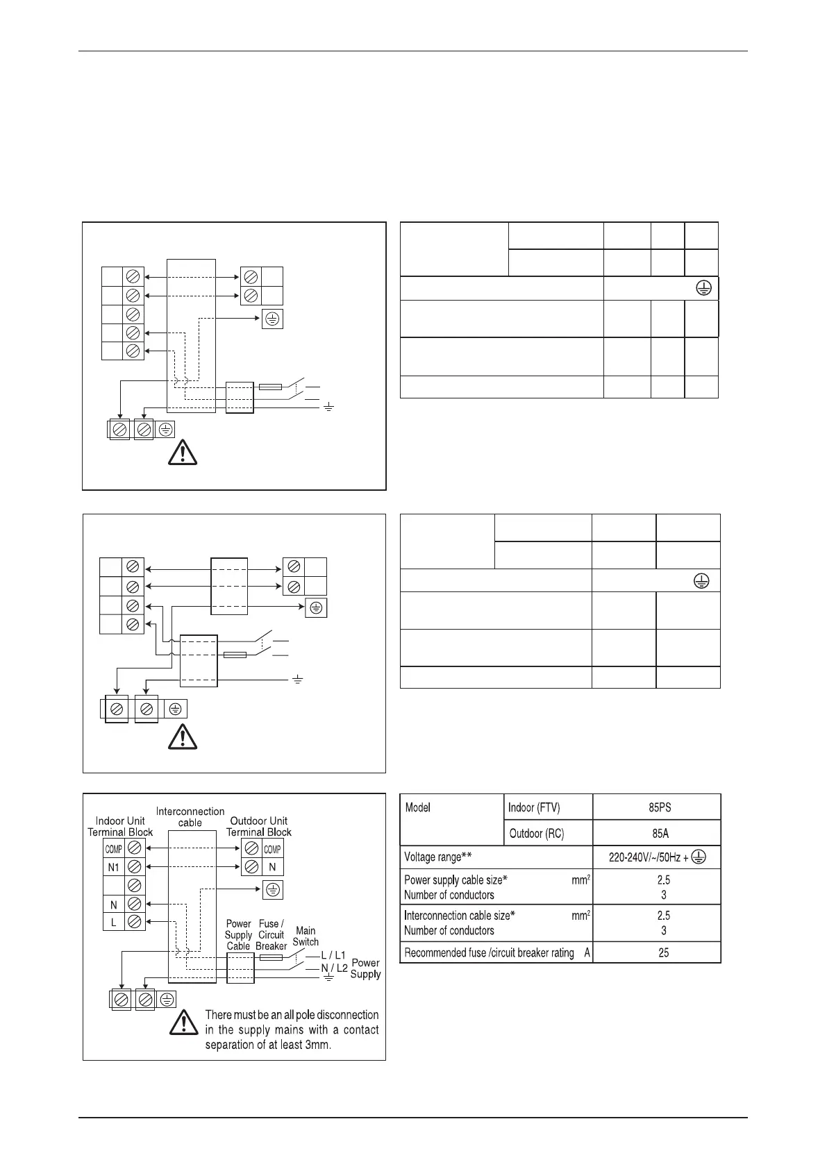
5. Wiring
IMPORTANT: * The figures shown in the table are for information purpose only. They should be checked
and selected to comply with the local/national codes of regulations. This is also subject to
the type of installation and conductors used.
** The appropriate voltage range should be checked with label data on the unit.
There must be an all pole disconnection
in the supply mains with a contact
separation of at least 3mm.
There must be an all pole disconnection
in the supply mains with a contact
separation of at least 3mm.
Outdoor Unit
Terminal Block
Interconnection
cable
Indoor Unit
Terminal Block
COMP
COMP
N
L
N / L2
L / L1
Power
Supply
Main
Switch
Fuse /
Circuit
Breaker
Power
Supply
Cable
N1
N
Model Indoor 28/35A 50A 60A
Outdoor 28/35A 50A 60A
Voltage range
**
220-240V/~/50Hz +
Power supply cable size
*
mm
2
Number of conductors
1.5
3
2.5
3
2.5
3
Interconnection cable size
*
mm
2
Number of conductors
1.5
3
2.5
3
2.5
3
Recommended fuse /circuit breaker rating A 16 20 20
Outdoor Unit
Terminal Block
Indoor Unit
Terminal Block
N
L
N / L2
L / L1
Power
Supply
Main Switch
Fuse / Circuit
Breaker
Power Supply Cable
Model Indoor
28/35P 50/60P
Outdoor
28/35F 50/60C
Voltage range
**
220-240V/~/50Hz +
Power supply cable size
*
mm
2
Number of conductors
1.5
3
2.5
3
Interconnection cable size
*
mm
2
Number of conductors
1.5
3
2.5
3
Recommended fuse /circuit breaker rating A
16 20
COMP
N1
N
COMP
Cooling Unit (single phase)
Interconnection
cable
 Loading...