Do you have a question about the Daikin FTX20K(2)V1B and is the answer not in the manual?
Lists all available functions for the specified models.
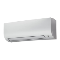
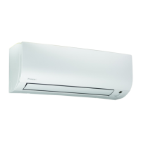
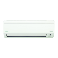
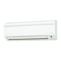
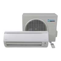
Details the technical specifications of the units.
Diagrams for indoor unit PCB connectors and components.
Diagrams for outdoor unit PCB connectors and components.
Explains primary operational functions like temperature and fan speed control.
Details the role and function of various thermistors in the system.
Outlines control specifications and logic for system operation.
Information and usage of the remote controller.
Common problems and initial checks for troubleshooting.
Troubleshooting guide based on LED indicators on indoor and outdoor units.
General procedures for diagnosing service issues.
Detailed troubleshooting steps for various error codes and malfunctions.
Specific checks and tests for components and systems.
Guidelines and procedures for servicing the unit.
Steps for conducting trial operation after installation.
Procedures for setting operational parameters in the field.
Guidance on applying silicone grease for heat dissipation.
Diagrams illustrating the refrigerant piping connections.
Diagrams showing the electrical wiring connections for the units.
Safety warnings and precautions for personnel performing maintenance.
Safety warnings and precautions for the end-users of the product.
Explains the meaning of various icons used in the manual.
Explains how the unit regulates room temperature.
Details how compressor frequency is controlled.
Describes how airflow direction is controlled for different modes.
Details the fan speed settings and automatic control for the indoor unit.
Explains the function of program dry operation for humidity control.
Describes how the unit automatically selects cooling or heating mode.
Explains the thermostat control logic based on temperature differences.
Details the NIGHT SET Mode for comfortable sleep and energy saving.
Explains the ECONO Operation for reducing power consumption.
Describes the POWERFUL Operation for maximum cooling and heating capacity.
Covers additional functions like Hot-Start and Auto-restart.
Role of the outdoor heat exchanger thermistor in system control.
Function of the discharge pipe thermistor for temperature control.
Role of the indoor heat exchanger thermistor in freeze-up protection.
Defines the hierarchy of operation modes including normal and forced operations.
Explains how compressor frequency is controlled based on temperature and other factors.
Details controls implemented during mode changes and start-up.
Controls compressor frequency based on discharge pipe temperature.
Manages compressor frequency based on input current to prevent overload.
Protects the indoor heat exchanger from freezing during cooling operation.
Prevents abnormal high pressure during heating by limiting compressor frequency.
Explains the control logic for the outdoor fan's speed and operation.
Protects the compressor from liquid compression by stopping operation.
Details the process and conditions for defrosting the outdoor unit.
Manages the electronic expansion valve for refrigerant flow control.
Describes detection methods for sensor malfunctions and overcurrent/overload.
Common problems and initial checks for troubleshooting.
Troubleshooting guide based on LED indicators on indoor and outdoor units.
General procedures for diagnosing service issues.
Detailed troubleshooting steps for various error codes and malfunctions.
Specific checks and tests for components and systems.
Lists error codes and their corresponding descriptions and reference pages.
Troubleshooting steps for indoor unit PCB abnormalities (Error Code A1).
Troubleshooting for freeze-up protection and heating peak-cut errors (Error Code A5).
Troubleshooting for fan motor abnormalities (Error Code A6).
Troubleshooting for indoor thermistor errors (Error Codes C4, C9).
Troubleshooting for voltage detection errors (Error Code U2).
Troubleshooting for communication errors between units (Error Code U4).
Troubleshooting for unspecified voltage issues between units (Error Code UA).
Troubleshooting for outdoor unit PCB malfunctions (Error Code E1).
Troubleshooting for compressor overload detection (Error Code E5).
Troubleshooting steps for compressor lock detection (Error Code E6).
Troubleshooting for DC fan motor lock detection (Error Code E7).
Troubleshooting for input overcurrent detection (Error Code E8).
Troubleshooting for four-way valve abnormalities (Error Code EA).
Troubleshooting for discharge pipe temperature control issues (Error Code F3).
Troubleshooting for high pressure control in cooling mode (Error Code F6).
Troubleshooting for compressor system sensor abnormalities (Error Code H0).
Troubleshooting for position sensor abnormalities affecting compressor start-up (Error Code H6).
Troubleshooting for outdoor unit thermistor errors (Error Codes H9, J3, J6, P4).
Troubleshooting for electrical box temperature rise (Error Code L3).
Troubleshooting for radiation fin temperature rise (Error Code L4).
Troubleshooting for output overcurrent detection (Error Code L5).
Procedures for checking thermistor resistance values.
Checks for indoor fan motor connector, voltage, and pulse signals.
Instructions for checking power supply waveforms for disturbances.
Steps to check the electronic expansion valve for continuity and operation.
Procedures to check the performance of the four-way valve.
Steps to check the refrigerant system for issues like leakage.
Guidance on using an inverter analyzer for diagnosis.
Checks rotation pulse input on the outdoor unit PCB.
Verifies installation conditions like space and airflow.
Procedure for checking the discharge pressure.
Checks the outdoor fan system for proper operation.
Tests for short circuits on the main circuit board.
Procedures for checking the power module.
Safety warnings and precautions for personnel performing maintenance.
Safety warnings and precautions for the end-users of the product.
Explains the meaning of various icons used in the manual.
| Cooling Capacity | 2.0 kW |
|---|---|
| Heating Capacity | 2.5 kW |
| Energy Efficiency Class (Cooling) | A++ |
| Energy Efficiency Class (Heating) | A+ |
| Refrigerant | R-32 |
| Type | Split |
| Noise Level (Indoor) | 19 dBA (Silent Mode) |