Do you have a question about the Daikin FTXF20D5V1B and is the answer not in the manual?
Details on the documentation set and its target audience.
Overview of the installer reference guide chapters and their content.
Details on the documentation set and safety guidelines.
Explanation of warning symbols used in the manual.
General guidelines and precautions for installers.
General safety precautions for installation personnel.
Requirements and restrictions for the installation location.
Specifications for room size and ventilation for R32 refrigerant.
Information regarding R410A or R32 refrigerant safety.
Electrical installation safety precautions and guidelines.
Safety instructions for installing the unit.
Precautions for selecting and preparing the installation site.
Safety guidelines for connecting refrigerant piping.
Introduction to box contents and handling instructions.
Information on unpacking the indoor unit.
Steps to remove accessories from the indoor unit packaging.
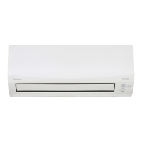
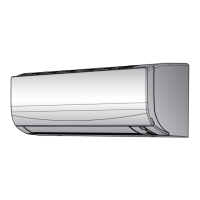
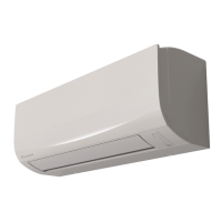
Diagram and explanation of the system components.
Temperature and humidity ranges for safe and effective operation.
Guidelines for selecting and preparing the installation location.
Specific requirements for the indoor unit installation site.
Procedure for opening the indoor unit for access.
Steps to remove the front panel of the indoor unit.
Procedure for reattaching the front panel.
Instructions for removing the front grille.
Steps for reattaching the front grille.
Procedure to remove the electrical wiring box cover.
Instructions for opening the service cover.
Steps for physically installing the indoor unit.
Important safety precautions during indoor unit installation.
Procedure for installing the mounting plate on the wall.
Instructions for drilling the wall hole for piping.
Procedure for removing the pipe port cover.
Ensuring proper drainage for condensation water.
Extending the drain hose with field-supplied parts.
Connecting rigid PVC pipe for drainage.
Connecting pipes on the right side of the unit.
Connecting pipes on the left side of the unit.
Procedure for checking water leaks after installation.
Requirements and materials for refrigerant piping.
Specifications for refrigerant piping materials and cleanliness.
Guidelines for insulating refrigerant piping.
Steps and precautions for connecting refrigerant piping.
Overview of the refrigerant piping connection process.
Safety precautions for connecting refrigerant piping.
Detailed instructions for connecting refrigerant pipes.
Best practices for bending refrigerant pipes.
Procedure for flaring the end of refrigerant pipes.
Final steps for connecting piping to the indoor unit.
Steps and precautions for electrical wiring connections.
Overview of the electrical wiring process.
Safety guidelines for electrical wiring.
Detailed procedures for electrical wiring connections.
Details on interconnection cable specifications.
Procedure for connecting wiring to the indoor unit.
Insulating drain, refrigerant, and interconnection piping.
Routing pipes through the wall hole.
Securing the indoor unit to the mounting plate.
Procedure to set different addresses for multiple indoor units.
Introduction to the commissioning process after installation.
List of checks to perform before system commissioning.
Steps for performing a system test run.
Procedure for test runs during winter operation.
Explaining operation, maintenance, and documentation to the user.
Guidelines for proper system disposal and compliance with regulations.
Information on the unit's wiring diagram and legend.
Explanation of symbols used in the wiring diagram.
Definitions of terms used in the manual.
| Model | FTXF20D5V1B |
|---|---|
| Category | Air Conditioner |
| Type | Wall Mounted |
| Cooling Capacity | 2.0 kW |
| Heating Capacity | 2.5 kW |
| Energy Efficiency Ratio (EER) | 3.21 |
| Energy Efficiency Rating (Cooling) | A++ |
| Energy Efficiency Rating (Heating) | A+ |
| Refrigerant | R32 |
| Indoor Unit Dimensions (WxHxD) | 770 x 286 x 225 mm |
| Indoor Unit Weight | 8.5 kg |
| Outdoor Unit Dimensions (WxHxD) | 658 x 550 x 275 mm |
| Power Supply | 220-240V / 50Hz |
| Indoor Unit Noise Level (Min) | 20 dB(A) |