2 | Components
Service manual
72
FTXF20~71A + FTXF20~25B + FTXF20~42C + ATXF20~71A + ATXF20~42C
+ RXF20~71A + RXF20~60B + RXF20~42C + ARXF20~71A + ARXF20~42C
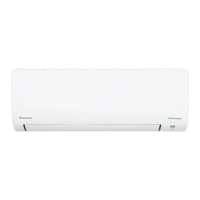
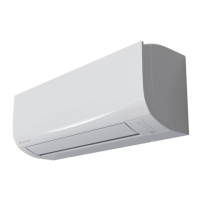
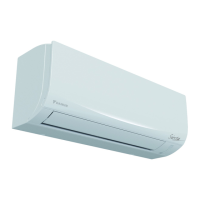
Split Sensira R32
ESIE18-12E – 2021.02
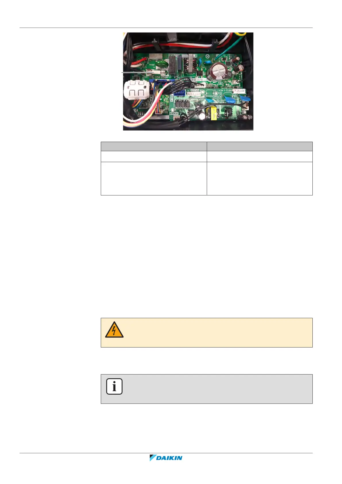
a Fuse
Is the problem solved? Action
Yes No further actions required.
No Return to "2.6.1Checking
procedures"[467] of the indoor unit
main PCB and continue with the next
procedure.
2.7 Inverter PCB
2.7.1 Checking procedures
As the inverter PCB is integrated in the main PCB of the unit, see "2.8 Main
PCB"[474] for the other check procedures.
To perform an electrical check of the inverter PCB
Prerequisite: Stop the unit operation via the user interface.
Prerequisite: Turn OFF the respective circuit breaker.
Prerequisite: Remove the required plate work, see "2.10Plate work"[4101].
1 Open the compressor insulation.
DANGER: RISK OF ELECTROCUTION
Wait for at least 10 minutes after the circuit breaker has been turned OFF, to be sure
the rectifier voltage is below 10VDC before proceeding.
2 Remove the cover of the compressor wire terminals.
3 Disconnect the wiring from the compressor wire terminals U, V and W.
INFORMATION
Note the position of the Faston connectors on the compressor wire terminals to
allow correct connection during installation.
Connect the Faston connectors to the Inverter Analyzer (SPP number 2238609).
 Loading...