Do you have a question about the Daikin FTXM-V Series and is the answer not in the manual?
Essential safety precautions and warnings for repair and maintenance personnel.
Explanation of icons used throughout the manual to convey important information.
Records of changes and updates made to the manual over time.
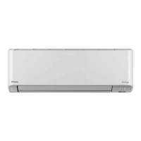
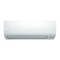
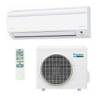
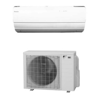
Lists the specific indoor and outdoor unit models covered by this manual.
Overview of the various functions and features available for the FTXM-V series.
Detailed technical specifications for indoor and outdoor units, including capacities and dimensions.
Diagrams and list of connectors on the indoor unit's control PCB.
Diagrams and list of connectors on the outdoor unit's main PCB.
Detailed explanation of the primary operational functions of the air conditioner.
Explanation of how room and set temperatures are managed for optimal comfort.
Details on how the inverter controls compressor frequency for capacity regulation.
Description of airflow control mechanisms like dual flaps and wide-angle louvers.
Explanation of the COMFORT AIRFLOW feature for enhanced air distribution.
Details on the hybrid cooling mode for efficient dehumidification and comfort.
How the unit automatically switches between cooling and heating modes.
Explanation of thermostat operation based on room temperature differences.
Instructions for setting up weekly operating schedules for the air conditioner.
Guidance on connecting the unit to a network for remote control.
Description of the role and function of various thermistors in the system.
Technical specifications for the unit's control logic and operation.
Overview of potential malfunctions and error detection methods.
Lists remote controllers compatible with the FTXM-V series.
Detailed explanation and operation of the ARC466A70 remote controller.
Detailed explanation and operation of the ARC466A71 remote controller.
Common issues, symptoms, and initial checks for troubleshooting.
Using LED indicators on indoor and outdoor units for fault diagnosis.
Step-by-step procedures for diagnosing issues using service modes.
Detailed troubleshooting steps for various error codes and system abnormalities.
Procedures for checking the condition and functionality of key components.
Procedure for safely removing refrigerant before unit relocation or disposal.
Procedure to force the unit into cooling mode for testing or maintenance.
Steps for performing initial operational tests after installation.
Configuration settings for specific installation environments and features.
Guidelines for applying silicone grease on power transistor/diode bridge during PCB replacement.
Schematic diagrams illustrating the refrigerant piping for indoor units.
Electrical wiring diagrams for indoor and outdoor units.
Defines the operational limits for cooling and heating based on temperature.
| Inverter | Yes |
|---|---|
| Series | FTXM-V Series |
| Refrigerant | R32 |
| Heating Seasonal Performance Factor (HSPF) | Up to 5.15 (depending on model) |
| Noise Level (Indoor Unit) | 19 dBA - 45 dBA (depending on model) |
| Power Supply | 220-240 V, 50 Hz |
| Operating Temperature (Cooling) | -10°C to 46°C |
| Operating Temperature (Heating) | -15°C to 24°C |