5
English
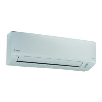
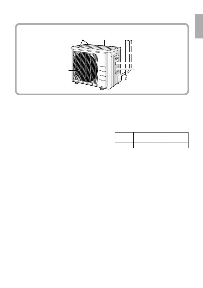
Outdoor Unit
Appearance of the outdoor unit may differ from some models.•
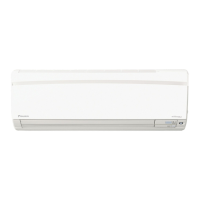
Indoor Unit
Air fi lter 1.
Titanium apatite photocatalytic 2.
air-purifying fi lter:
These fi lters are attached to the inside of •
the air fi lters.
Air inlet3.
Front panel4.
Panel tab5.
Room temperature sensor:6.
It senses the air temperature around the •
unit.
Display7.
Air outlet8.
Flap (horizontal blade): 9. (page 11)
Louvers (vertical blades):10.
The louvers are inside of the air outlet. •
(page 12)
Model name plate11.
Indoor unit ON/OFF switch:12.
Press this switch once to start operation. •
Press once again to stop it.
The operation mode refers to the following •
table.
Mode
Temperature
setting
Airfl ow rate
AUTO 25°C AUTO
This switch is useful when the remote •
controller is missing.
OPERATION lamp (green)13.
TIMER lamp (yellow): 14. (page 16)
Signal receiver:15.
It receives signals from the remote controller.
•
When the unit receives a signal, you will •
hear a beep sound.
Operation start• .............beep-beep
Settings changed• .........beep
Operation stop• .............long beep
Outdoor Unit
Air inlet (back and side)16.
Refrigerant piping and inter-unit wiring17.
Drain hose18.
Earth terminal:19.
It is inside of this cover.•
Air outlet20.
Outdoor temperature sensor (back)21.
Model name plate22.
01_EN_3P272441-5.indb 501_EN_3P272441-5.indb 5 11/30/2010 4:01:25 PM11/30/2010 4:01:25 PM

 Loading...