English
1-13
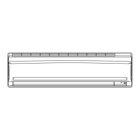
IR Signal Receiver
When an infrared remote control operating signal has been
transmitted, the signal receiver on the indoor unit will respond
as below to confi rm acceptance of the signal transmission.
LED Indicator Lights for Heat Pump Unit
IR Receiver
Heat Pump Unit
The table shows the LED indicator lights for the air conditioner
unit under normal operation and fault conditions.
The LED indicator lights are located at the right bottom of
the air conditioner unit.
The heat pump units are equipped with an “auto” mode
sensor whereby it will provide reasonable room temperature
by switching automatically to either “cool” or “heat” mode
according to the temperature set by the user.
ON/OFF
Cool/Heat
Timer
Sleep
ON/OFF switch
Additional Charge
The refrigerant is pre-charged in the outdoor unit. If the piping length is less than 7.5m, then additional charge after vacuuming
is not necessary. If the piping length is more than 7.5m, then use the additional charge value as indicated in the table.
IR Receiver
INDICATOR LIGHTS
ON to OFF 1 Long Beep
OFF to ON
Pump down/Cool force on
2 Short Beep
Others 1 Short Beep
Example:
FTYN25LV1B & RYN25LV1B with 12m piping length, additional piping length is 4.5m. Thus,
Additional charge = 4.5[m] x 16[g/m]
= 72.0[g]
Additional refrigerant charge [g] per additional 1m length as tabulated.
Indoor FTYN25/35LV1B FTYN50/60LV1B
Outdoor RYN25/35LV1B RYN50/60LV1B
Additional charge [g/m] 16 16
1 EN-5WMJ-1211(0)Daikin.indd 131 EN-5WMJ-1211(0)Daikin.indd 13 1/12/12 1:44:39 PM1/12/12 1:44:39 PM
 Loading...