

M
Michele LozanoAug 2, 2025
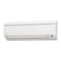
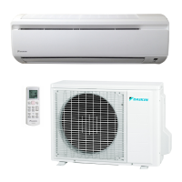
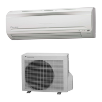
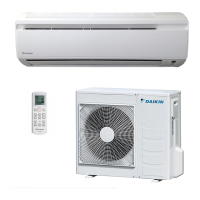
What to do if my Daikin FTYN25LV1B Air Conditioner unit does not operate?
- CChristopher CoxAug 2, 2025
If your Daikin Air Conditioner unit isn't operating, here are a few things to check: - Check the power supply, as there may be a power failure or a blown fuse. - Ensure the power plug is properly connected; reconnect it if it's loose. - Verify the delay timer setting to make sure it's correctly configured.