1-7
English
VALVE
N1 N L
3 way valve
Relay (220-240V, 10A)
Chiller
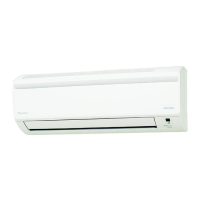
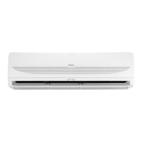
FWT02/03/04/05/06
FCU3
3wv
x1
FCU2
3wv
x2
FCU1
3wv
x3
N
T
S
R
x1x2x3
3WV
IR Signal Receiver
When an infrared remote control operating signal has been
transmitted, the signal receiver on the indoor unit will respond
as below to confirm acceptance of the signal transmission.
LED Indicator Lights for Cooling Unit/Heat Pump Unit
Cooling Unit/Heat Pump Unit
The table shows the LED indicator lights for the air conditioner
unit under normal operation and fault conditions.
The LED indicator lights are located at the right bottom of
the air conditioner unit.
IR Receiver
ON/OFF
Cool/Heat
Timer
Sleep
ON/OFF switch
IR Receiver
INDICATOR LIGHTS
ON to OFF 1 Long Beep
OFF to ON
Pump down/Cool force on
2 Short Beep
Others 1 Short Beep
LED Indicator Lights: Normal Operation And Fault Conditions For Cooling/Heat Pump Unit
COOL/HEAT
(GREEN/RED)
Normal Operation/Fault Indication Action Error Code
Green
Cool mode - -
Red
Heat mode - -
Timer on - -
Sleep mode on - -
Fan mode on - -
Dry mode on - -
1 time
Room air sensor contact
Loose/Short
Call your dealer Blink E1
2 times
Indoor coil sensor open/short Call your dealer Blink E2
3 times
Pipe water temperature poor - Blink E4
1 time
Pipe water temperature bad - Blink E5
6 times
Hardware error (tact switch pin short) Call your dealer Blink E8
4 times
No feedback from indoor fan Call your dealer Blink E9
ON
ON or OFF
Blinking
VALVE
N1 N L
VALVE
N1 N L
1 IM-WMJW-0312(9)DKdenv_EN.indd 7 1/31/20 4:23:46 PM
 Loading...