English 11
3.
When including BS unit
NOTENOTENOTENOTE
• It is not necessary to designate indoor unit address when
using group control. The address is automatically set when
power is activated.
[ PRECAUTIONS ]
1. A single switch can be used to supply power to units on the
same system. However, branch switches and branch circuit
breakers must be selected carefully.
2. Do not ground the equipment on gas pipes, water pipes or
lightning rods, or crossground with telephones. Improper
grounding could result in electric shock.
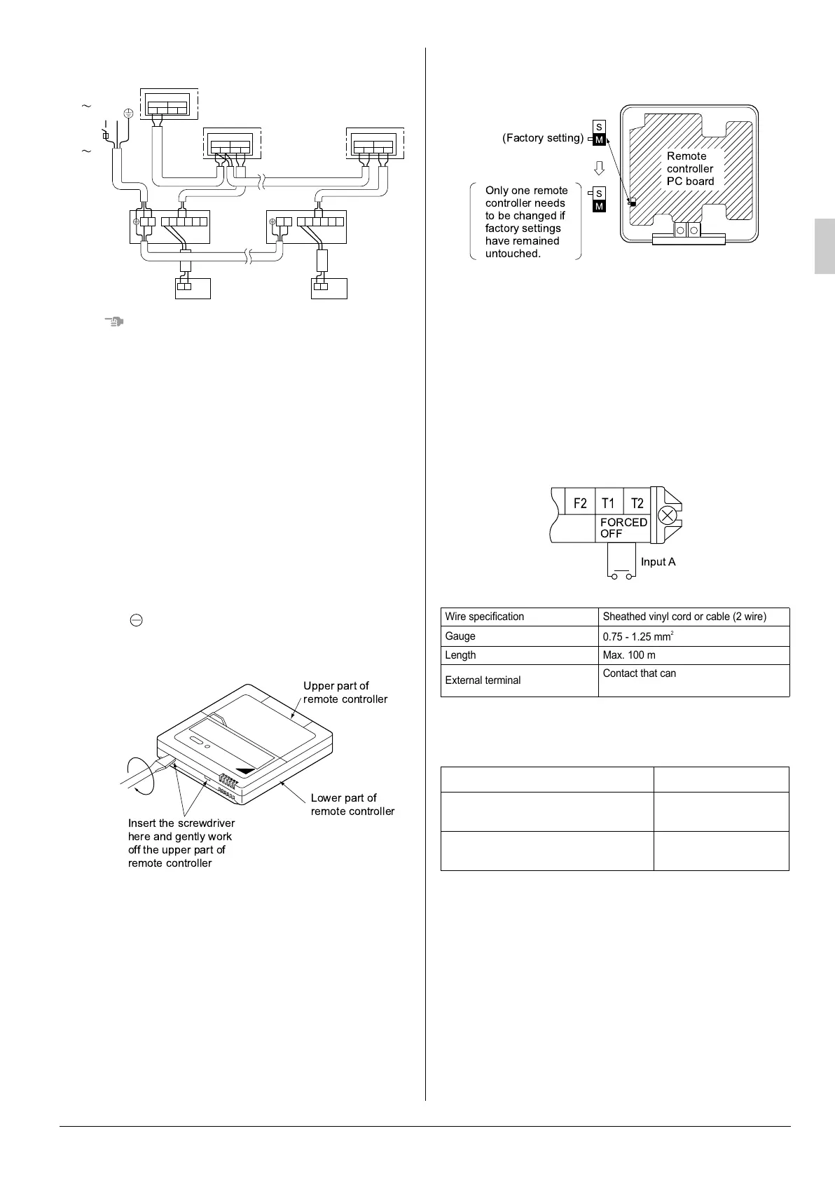
9-3 Control by 2 Remote Controllers (Controlling 1
indoor unit by 2 remote controllers)
• When using 2 remote controllers, one must be set to “MAIN”
and the other to “SUB”.
MAIN/SUB CHANGEOVER
(1) Insert a screw driver into the recess between the upper
and lower part of remote controller and, working from the 2
positions, pry off the upper part. The remote controller PC
board is attached to the upper part of remote controller.
(2) Turn the MAIN/SUB changeover switch on one of the two
remote controller PC boards to “S”. (Leave the switch of the
other remote controller set to “M”.)
Wiring Method (See ‘‘ELECTRIC WIRING WORK’’)
(3) Remove the electric parts box lid
(4) Add remote control 2 (slave) to the terminal block for
remote controller (P
1
, P
2
) in the electric parts box.
(There is no polarity.) (Refer to Fig. 30 and 8-3.)
9-4 FOR REMOTE CONTROL (FORCED OFF AND
ON/OFF OPERATION)
(1) Wire specifications and how to perform wiring
• Connect input from outside to terminals T1 and T2 of the
terminal block for remote controller.
(2) Actuation
• The following table explains FORCED OFF and ON/OFF
OPERATIONS in response to Input A.
(3) How to select FORCED OFF and ON/OFF OPERATION
• Turn the power on and then use the remote controller to
select operation.
9-5 CENTRALIZED CONTROL
• For centralized control, it is necessary to designate the group
No. For details, refer to the manual of each optional control-
lers for centralized control.
IN/D OUT/D
F
1
F
2
F
1
F
2
IN/DOUT/D
F
1
F
2
F
1
F
2
LN
P
1
P
2
P
1
P
2
F
1
F
2
T
1
T
2
BS unit
No. 3
System
Outdoor unit
Power
supply
220-240V
50Hz
or
220V
60Hz
Indoor unit A
Most
downstream
indoor unit
Control box
Control box
IN/DOUT/D
F
1
F
2
F
1
F
2
BS unit
Control box
P
1
P
2
P
1
P
2
F
1
F
2
T
1
T
2
LN LN
Upper part of
remote controller
Lower part of
remote controller
Insert the screwdriver
here and gently work
off the upper part of
remote controller
Wire specification Sheathed vinyl cord or cable (2 wire)
Gauge
0.75 - 1.25 mm
2
Length Max. 100 m
External terminal
Contact that can ensure the minimum
applicable load of 15 V DC, 1 mA.
FORCED OFF ON/OFF OPERATION
Input “ON” stops operation (impossible by
remote controllers.)
Input OFF
→
ON turns ON
unit.
Input OFF enables control by remote
controller.
Input ON
→
OFF turns OFF
unit.
01_EN_3P172532-7B.fm Page 11 Wednesday, October 14, 2015 6:17 PM
 Loading...