English 7
Use “ Table 2 ” as a reference if a torque wrench is not available.
Once work is complete, make sure there is no gas leaking. As
the flare nut is tightened with the wrench, the torque will sud-
denly increase. From that position, tighten the nut to the angle
shown on “ Table 2 ”.
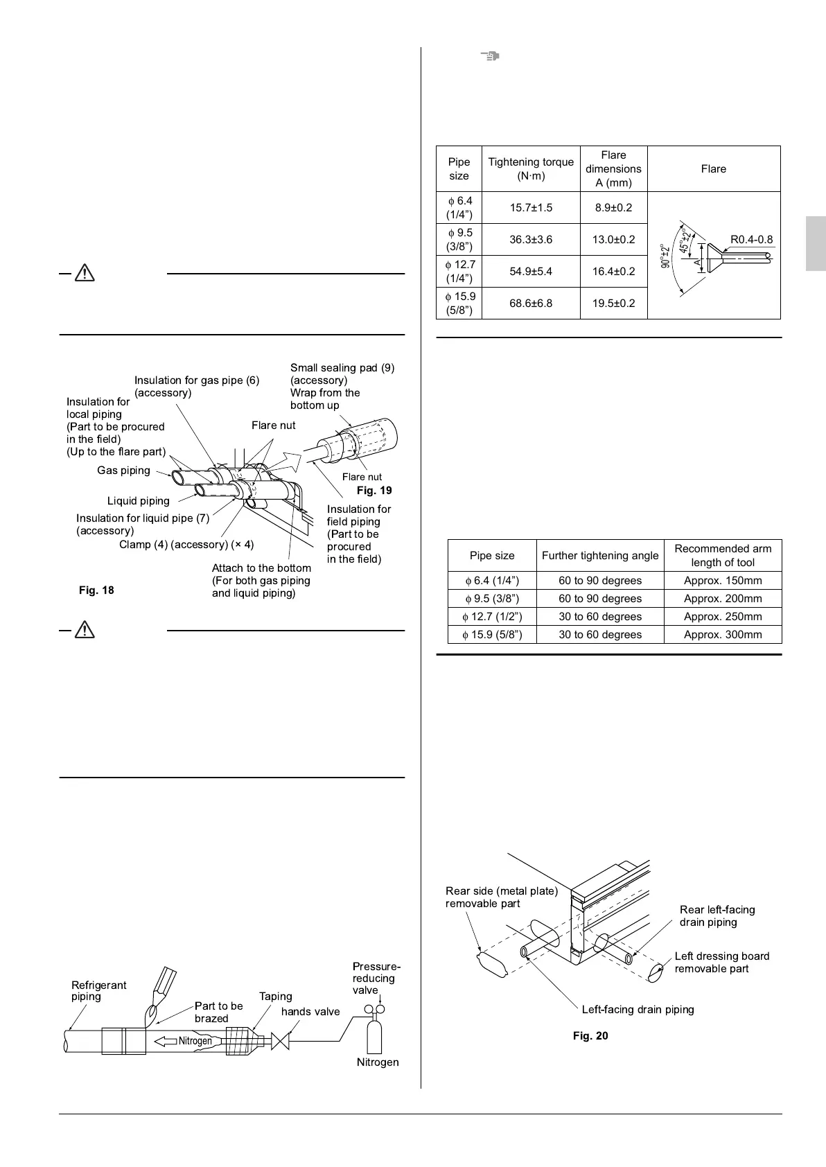
• Make absolutely sure to execute heat insulation works on the
pipe-connecting section after checking gas leakage by thor-
oughly studying the following figure and using the attached
heat insulating materials for fitting (6) and (7). (Fasten both
ends with the clamps (4) (accessory).)
(Refer to Fig. 18)
• Wrap the sealing pad (9) (accessory) only around the insula-
tion for the joints on the gas piping side.
(Refer to Fig. 19)
CAUTION
Be sure to insulate any field piping all the way to the piping
connection inside the unit. Any exposed piping may cause
condensation or burns if touched.
CAUTION
CAUTION TO BE TAKEN WHEN BRAZING REFRIGER-
ANT PIPING
Do not use flux when brazing refrigerant piping. Therefore, use
the phosphor copper brazing filler metal (BCuP-2: JIS Z 3264/
B-Cu93P-710/795: ISO 3677) which does not require flux.
(Flux has extremely harmful influence on refrigerant piping
systems. For instance, if the chlorine based flux is used, it will
cause pipe corrosion or, in particular, if the flux contains fluo-
rine, it will damage the refrigerant oil.)
• Before brazing local refrigerant piping, nitrogen gas shall be
blown through the piping to expel air from the piping.
If your brazing is done without nitrogen gas blowing, a large
amount of oxide film develops inside the piping, and could
cause system malfunction.
• When brazing the refrigerant piping, only begin brazing after
having carried out nitrogen substitution or while inserting
nitrogen into the refrigerant piping. Once this is done, con-
nect the indoor unit with a flared or a flanged connection.
• Nitrogen should be set to 0.02 MPa with a pressure-reducing
valve if brazing while inserting nitrogen into the piping.
NOTENOTENOTENOTE
The flare nuts used must be those included with the main
body.
• Refer to Table 1 for tightening torque.
Tabl e 1
Not recommendable but in case of emergency
You must use a torque wrench but if you are obliged to
install the unit without a torque wrench, you may follow the
installation method mentioned below.
After the work is finished, make sure to check that
there is no gas leak.
When you keep on tightening the flare nut with a spanner,
there is a point where the tightening torque suddenly
increases. From that position, further tighten the flare nut
the angle shown below:
Tabl e 2
7. DRAIN PIPING WORK
Rig the drain pipe as shown below and take measures against
condensation. Improperly rigged piping could lead to leaks and
eventually wet furniture and belongings.
(1) Carry out the drain piping
• For drain work, rig the pipes so that they drain reliably.
• The drain pipe outlet direction can be chosen from the
right rear, right, left rear, and left. Refer to “REFRIGER-
ANT PIPING WORK” for right rear and right direction,
and refer to Fig. 20 for left rear and left direction.
!
" # $ #
%
Fig. 18
Fig. 19
Pipe
size
Tightening torque
(N·m)
Flare
dimensions
A (mm)
Flare
φ 6.4
(1/4”)
15.7±1.5 8.9±0.2
φ 9.5
(3/8”)
36.3±3.6 13.0±0.2
φ 12.7
(1/4”)
54.9±5.4 16.4±0.2
φ 15.9
(5/8”)
68.6±6.8 19.5±0.2
Pipe size Further tightening angle
Recommended arm
length of tool
φ 6.4 (1/4”) 60 to 90 degrees Approx. 150mm
φ 9.5 (3/8”) 60 to 90 degrees Approx. 200mm
φ 12.7 (1/2”) 30 to 60 degrees Approx. 250mm
φ 15.9 (5/8”) 30 to 60 degrees Approx. 300mm
A
45
0
±
2
0
R0.4-0.8
90
0
±
2
0
Rear side (metal plate)
removable part
Left-facing drain piping
Left dressing board
removable part
Rear left-facing
drain piping
Fig. 20
01_EN_3P172532-7B.fm Page 7 Wednesday, October 14, 2015 6:17 PM
 Loading...