•VRV
®
Systems • Indoor Units
11
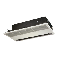
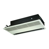
• Indoor Units • CEILING MOUNTED CORNER CASSETTE • FXKQ-MAVE
8 Wiring diagram
8 - 1 Wiring diagram
FXKQ-MA
3D039564B
Power supply
Electric parts box
Note 2
Input from outside
Note 1
Transmission wiring central
remote control
Wired remote control
(Optional accessory)
220-240V
~
50Hz
220V
~
60Hz
Note 3
NOTES
1 In case using central remote control, connect it to the unit in accordance with the attached instruction manual.
2 When connecting the input wires from outside, forced off or on/off control operation can be selected by remote control.
In details, refer to the installation manual attached the unit.
3 In case high E.S.P. operation, change over the wiring connection from X2A to X3A.
4 Use copper conductors only.
Indoor Unit R1T Thermistor (Air)
A1P Printed circuit board R2T•R3T Thermistor (Coil)
A2P Terminal board S1Q Limit switch (Swing flap)
C1R Capacitor (M1F) T1R Transformer (220-240V/22V)
F1U Fuse (훾, 5A, 250V) X1M Terminal block (Power)
HAP Light emitting diode (Service monitor-green) X2M Terminal block (Control)
K1R-K3R Magnetic relay (M1F) Y1E Electronic expansion valve
KAR Magnetic relay (M1S) Wired remote control
KPR Magnetic relay (M1P) R1T Thermistor (Air)
M1F Motor (Indoor fan) SS1 Selector Switch (Main/Sub)
M1P Motor (Drain pump) Connector for optional parts
M1S Motor (Swing flap) X16A Connector (Adapter for wiring)
Q1M Thermo switch (M1F embedded) X18A Connector (Wiring adapter for electorical appendices)
COLORS : BLK : Black PNK : Pink
BLU : Blue RED : Red
BRN : Brown WHT : White
GRY : Gray YLW : Yellow
ORG : Orange
,
: Terminal block
: Connector
: Terminal
: Field wiring
 Loading...