LREQ5~20B7Y1
Air cooled refrigeration condensing unit
4PW74302-1D – 2016.11
Installation manual
4
3. SELECTION OF LOCATION
Select a location for installation that meets the following conditions.
Get the customer’s permission.
1. There is no danger of fire due to leakage of inflammable gas.
2. Select the location of the unit in such a way that neither the
discharged air nor the sound generated by the unit disturb anyone.
3. The foundation is strong enough to support the weight of the unit
and the floor is flat to prevent vibration and noise generation.
4. The piping length between the outdoor unit and the indoor unit may
not exceed the allowable piping length.
(Refer to "6. REFRIGERANT PIPING" on page 6)
5. Locations where the unit’s suction vent and outlet vent do not
generally face the wind.
Wind blowing directly into the suction or outlet vents will interfere
with the unit’s operation.
If necessary, install some kind of obstruction to block the wind.
6. The space around the unit is adequate for servicing and the
minimum space for air inlet and air outlet is available.
(See the "Installation Space Examples" on page 4 for the minimum
space requirements.)
Installation Space Examples
• The installation space requirement shown in the following figure is
a reference for cooling operation when the outdoor temperature is
32°C.
If the design outdoor temperature exceeds 32°C or the heat load
exceeds maximum capacity in all the outdoor unit, take an even
large space on the intake shown in the following figure.
• During installation, install the units using the most appropriate of
the patterns shown in the following figure for the location in
question, taking into consideration human traffic and wind.
• If the number of units installed is more than that shown in the
pattern in the following figure, install the units so there are no short
circuits.
• As regards space in front of the unit, consider the space needed for
the local refrigerant piping when installing the units.
• If the work conditions in the following figure do not apply, contact
your dealer or Daikin directly.
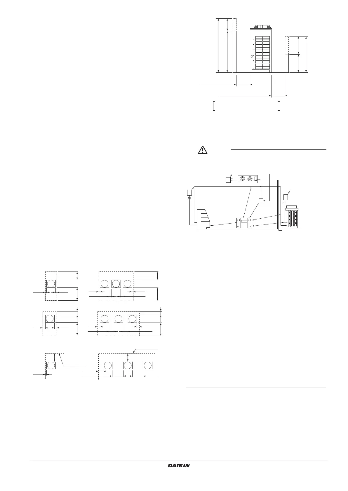
NOTE) For patterns 1 and 2
• Wall height for front side no higher than 1500 mm.
• Wall height on the suction side no higher than 500 mm.
• Wall height for sides – no limit
• If the height is exceeded the above, calculate h1 and h2 shown
in the figure below, and add h1/2 to the service space of front
side and h2/2 to the service space of suction side.
1. An inverter condensing unit may cause electronic noise generated
from AM broadcasting. Examine where to install the main
condensing unit and electric wires, keeping proper distances away
from stereo equipment, personal computers, etc.
Particularly for locations with weak reception, ensure there is a
distance of at least 3 meters for indoor remote controllers, place
power wiring and transmission wiring in conduits, and ground the
conduits.
2. When installing in a locations where there is heavy snowfall,
implement the following snow measures.
• Ensure the base is high enough that intakes are not clogged by
snow.
• Mount a snow protection hood (optional accessory)
• Remove the rear intake grille to prevent snow from
accumulating on the fins.
3. If condensate may drip on downstairs (or walkway) depending on
the floor condition, take a measure such as the installation of
central drain pan kit (sold separately).
4. The refrigerant R410A itself is nontoxic, nonflammable and is safe.
If the refrigerant should leak however, its concentration may
exceed the allowable limit depending on room size. Due to this it
could be necessary to take measures against leakage.
See “Engineering Data” for details.
<
If installed as a single unit
>
3DWWHUQ127(
3DWWHUQ
3DWWHUQ
3DWWHUQ127(
<
>
Front
side
Front side
Front side
Front side
Front
side
Front side
1ROLPLWWR
wall height
1ROLPLWWR
wall height
Service space
of suction side
Service space
of front side
Service space
of suction side
Service space
of front side
Service space
of suction side
Service space
of front side
Service space
of suction side
Service space
of front side
A
B
1500
500 h2
Front side
Service space
Service space
Suction side
h1
h1 = A (Actual height) – 1500
h2 = B (Actual height) – 500
X = 500 + h1/2 or over
Y = 300 + h2/2 or over
(Y = 100 + h2/2 or over)
[Values in parentheses are for pattern 2]
Branch switch,
overcurrent breaker
(Earth leakage breaker)
Branch switch,
overcurrent breaker
(Earth leakage breaker)
Control panel
Warning panel
Showcase
4PWEN74302-1D.book Page 4 Thursday, April 27, 2017 9:01 PM
 Loading...