LRYEQ16A7Y1 + LCBKQ3AV1(E)
CONVENI-PACK
4P448940-1A – 2016.07
Operation manual
16
2. Installation failure (Installation and environ-
mental problems)
• The unit is not installed on a stable horizontal
plane.
∗ The unit is not fixed securely.
• The environmental conditions of the place of
installation differ from normal atmospheric
conditions.
∗
Briny air environment, shore side, oil mist
environment, kitchen exhaust side, other cor-
rosive gas and adhesive mist environment.
• The place of installation had poor ventilation
and heat dissipation.
∗ The machine took in exhausted air again.
3. Work failure
• The interior of the piping was not vacuum
dried sufficiently.
∗ The clogging of the thin areas of the piping
caused by icing.
• The interior of the piping was not sufficiently
airtight.
∗ Leakage of refrigerant gas.
• The interior of the piping was contaminated
with foreign substance.
∗ The clogging of the thin areas of the piping.
• The unit was adversely affected by on-site
modification work.
∗
The use of the unit beyond the operating tem-
perature range as a result of on-site modifica-
tion.
• An accident resulted from the improper han-
dling of the unit under installation work.
∗ The loosening or wobbling of the outer panel
or broken or bent damage to the piping.
4. Operational failure
• Temperature settings for stored objects were
wrong.
∗ The storage of vegetables at temperatures
below 0°C.
• The periodical maintenance of the unit was
neglected.
∗ The clogging of the air heat exchanger, rust
generation from each part, gas leakage, and
icing of the indoor unit (showcase and unit
cooler).
5. Others
• Improvements recommended by our dealer in
advance were not accomplished.
∗ The simultaneous starting and stopping of a
number of units.
• Accidents were caused by natural disaster or
fire.
∗
Damage to electrical parts caused by lightning.
• There were other installation and operational
problems beyond common sense.
∗ The use of the unit without heat insulation
work on the piping.
• Work was conducted without keeping the fol-
lowing showcase restrictions.
<Showcase restrictions>
· The design pressure for the indoor unit is
2.5 MPa or more.
· The installation of the thermostatic expan-
sion valve and liquid supply solenoid valve
(both of which are for R410A) on a show-
case basis.
Thermal insulation of feeler tube of thermo-
static expansion valve must be thermal insu-
lated.
· Install showcases on the same floor if the show-
cases are connected to a single outdoor unit.
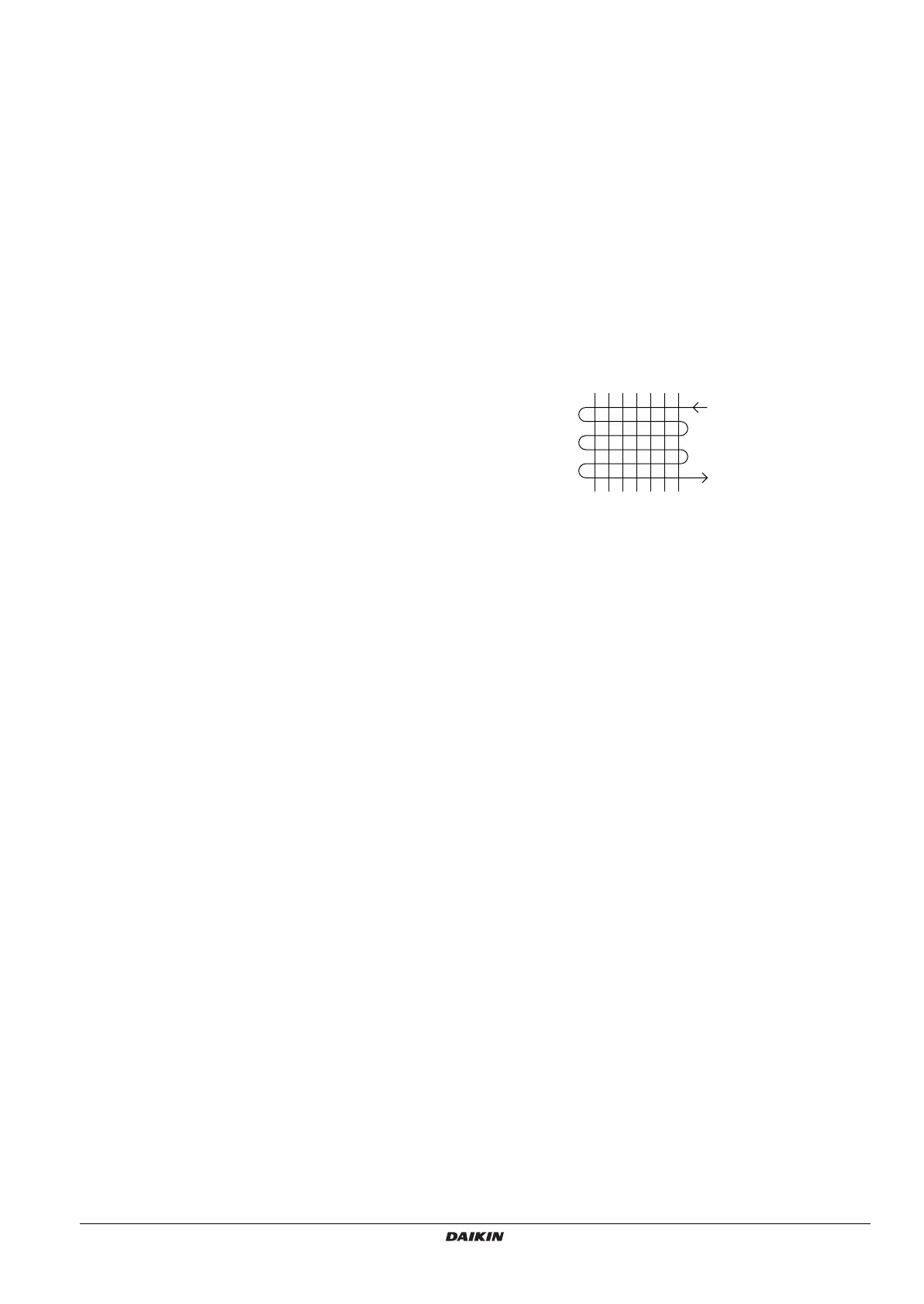
· Make sure that the outlet of piping used for
the heat exchanger is located downward (as
shown on the following figure).
Inlet
(upper side)
Outlet
(lower side)
Heat exchanger
4PEN448940-1A.book Page 16 Thursday, August 25, 2016 11:23 AM
 Loading...