EasyManua.ls Logo

Daikin LXE10E-1 Service Manual

Daikin LXE10E-1
164 pages
To Next Page IconTo Next Page
Page #1 background imageLoading...
Page #1 background image
TR03-06
(2003.12.00200)NK
$5,00
DAIKIN CONTAINER
LXE10E-1
TR 03-06
Service Manual
Head Office. Umeda Center Bldg., 4-12, Nakazakinishi 2-chome, Kita-ku, Osaka, 530-8323 Japan.
Tel: 06-6373-4338 (From overseas 81-6-6373-4338)
Fax: 06-6373-7297 (From overseas 81-6-6373-7297)
Tokyo Office. Tokyo Opera City Tower 12F. 3-20-2 Nishi-Shinjuku, Shinjuku-ku, Tokyo 163-1412, Japan.
Tel: 03-5353-7860 (From overseas 81-3-5353-7860)
Fax: 03-5353-7913 (From overseas 81-3-5353-7913)
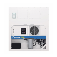
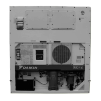
Marine type Container Refrigeration Unit Service Manual LXE10E-1
Container Refrigeration Unit
Marine type
https://daikin-p.ru

Table of Contents

Other manuals for Daikin LXE10E-1

Questions and Answers:

Daikin LXE10E-1 Specifications

General IconGeneral
BrandDaikin
ModelLXE10E-1
CategoryRefrigerator
LanguageEnglish

Summary

DANGER Safety Precautions

WARNING Safety Precautions

CAUTION Safety Precautions

1. Introduction to Daikin Container Unit

1.1 Unit Operation Range

Specifies the operational limits for ambient temperature, cooling water, voltage, and vibration.

2. General Description of LXE10E-1 Unit

2.1 Main Specifications

Lists key technical specifications of the LXE10E-1 model, including system, power, and refrigerant.

2.2 Component Identification

Identifies and lists the main external, internal, and control box components of the unit.

2.5 Unit Operation Modes and Control

2.5.1 Frozen Mode Operation

Details the control state transitions and common operations for frozen mode.

2.5.2 Chilled Mode Operation

Details the control state transitions and common operations for chilled mode.

2.5.3 Defrosting Mode Operation

Explains the defrosting process and control logic.

3. Electronic Controller Overview

3.1 Controller Function Table

A table listing the functions and features of the DECOS 3d controller.

3.2 Controller Operation Basics

Explains how to operate the unit using the electronic controller's panel.

3.3 Unit Operation Procedures

3.3.1 Operation Procedure Flow Chart

A flowchart illustrating the sequence of operations for the unit.

3.3.2 Mode Operation Procedures

Explains how to navigate and use different operation modes on the controller.

3.4 Alarm Display and Sensor Back-up

3.4.1 Alarm List

A comprehensive list of alarm codes, their content, and possible causes.

3.4.2 Back-up Operation at Sensor Malfunction

Details the unit's behavior when specific sensors malfunction.

3.5 Battery System

3.5.1 Battery Specifications

Details the specifications of the rechargeable battery used.

3.6 PC Communication and Data Management

3.6.1 Data Logging

Describes the types of operational data that can be logged by the unit.

3.6.2 Software Configuration

Outlines the software configuration options for data management and unit settings.

3.7 Electronic Controller Inspection Procedures

3.8 Controller Replacement and Initial Setup

3.8.1 Controller Replacement Procedure

Step-by-step procedure for physically replacing the controller unit.

3.8.2 Initial Setting & Operation

Guide to the initial setup and basic operation procedures after controller replacement.

3.9 PTI and Periodic Inspection

3.9.1 Inspection Items

Lists the specific items to be inspected during PTI and periodic maintenance.

3.9.2.1 PTI Selection Mode

Explains how to select the type of PTI (Short, Full, Manual Check).

3.9.2.2 Short PTI (S.PTI)

Details the steps and content of the Short PTI (S.PTI) inspection.

3.9.2.3 Full PTI (F.PTI)

Details the steps and content of the Full PTI (F.PTI) inspection.

3.10 Chartless Functionality

3.10.1 Chart Indication Mode

Explains how to display temperature log data in a graphic chart format.

3.10.2 P Code (Pull Down Time)

Describes the P code display for pull-down time during operation.

3.10.3 Chartless Code Display

Explains the chartless codes (H, d, P) for indicating operational status.

3.11 Communication Modem

4. Service and Maintenance

4.1 Maintenance Service Procedures

Covers essential maintenance tasks like refrigerant collection and gauge manifold use.

4.1.2 Gauge Manifold Usage

Instructions for attaching and removing the gauge manifold for pressure checks.

4.1.3 Automatic Pump Down

Explains the automatic pump down function and its operational procedure.

4.1.4 Refrigerant Recovery and Charge

Procedures for recovering refrigerant and charging the system.

4.2 Major Components and Maintenance

4.2.1 Scroll Compressor Maintenance

Details on the scroll compressor, including preparation and removal.

4.2.2 Fan and Fan Motor Servicing

Instructions for the maintenance and replacement of fans and fan motors.

4.2.4 Electronic Expansion Valve Replacement

Procedure for replacing the electronic expansion valve coil.

4.2.21 Evacuation and Dehydrating

Procedures for evacuating and dehydrating the system after repair.

5. Additional Devices

5.1 USDA Transportation

Details on using USDA receptacles and sensors for transportation.

6. Troubleshooting Unit Malfunctions

6.1 Refrigeration & Electrical System Issues

Table of malfunctions, abnormal points, and possible causes for the refrigeration and electrical systems.

6.2 Controller Alarm Codes

Lists alarm codes generated by the electronic controller and their potential causes.

6.4 Emergency Operation Procedures

Procedures for operating the unit in emergency situations.

7. Appendix and Technical Data

7.1 Bolt Tightening Torques

Lists standard torque values for tightening various bolts.

7.4 Coil Resistance Values

Provides resistance values for motor and solenoid valve coils.

7.6 HFC134a Pressure-Temperature Data

Table showing temperature-vapor pressure characteristics for HFC134a.

7.11 Refrigerant Piping Diagram

A schematic diagram illustrating the unit's refrigerant piping.

Related product manuals