Do you have a question about the Daikin LXE10E-A31 and is the answer not in the manual?
Defines the operating temperature and voltage ranges for the unit, along with vibration and shock limits.
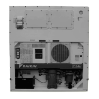
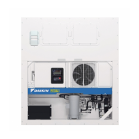
Illustrates and labels the main external components of the refrigeration unit.
Details the main technical specifications of the LXE10E model, including cooling system, power, and components.
Lists and labels the external components of the LXE10E unit, providing a visual guide.
Identifies and labels the internal components of the LXE10E unit, including sensors and fans.
Details the components located inside the control box, including PCBs, fuses, and contactors.
Details the actuation, set point, detection method, and symbol for the high-pressure switch.
Specifies set points and conditions for discharge gas temperature protection.
Details the current control parameters, including Hz and Amps for 50Hz and 60Hz operation.
Details the setting temperature, control sensor, and operation description for the Frozen mode.
Details the setting temperature, control sensor, and operation description for the Partial frozen mode.
Details the setting temperature, control sensor, and operation description for the Chilled mode.
Specifies the adjustable range for dehumidification, from 60%RH to 95%RH.
Allows setting the maximum KVA for generators to reduce total power consumption.
Describes the automatic execution of the pump down procedure.
Enables dehumidification mode and allows adjustment of inside humidity settings.
Provides a comprehensive list of alarm codes, their content, and the corresponding actions taken by the unit.
Details the specifications for both Alkaline and Rechargeable batteries used with the controller.
Explains the functions supported by the battery when main power is off, such as display wake-up and data logging.
Provides instructions and visual guidance for replacing both Alkaline and Rechargeable batteries.
Step-by-step instructions for replacing the coil of the electronic expansion valve.
Step-by-step instructions for replacing the body of the electronic expansion valve.
Presents a detailed schematic diagram of the unit's refrigeration piping system.
Provides a detailed schematic of the unit's electrical wiring, labeling components and connections.
Offers a stereoscopic view of the unit's wiring diagram for better spatial understanding.
Explains the meaning of index symbols (A, B, C) used to rank the importance of spare parts.
Explains how nominal horse power is indicated in the model name (e.g., 5 HP, 10 HP).
Details the designation for condenser cooling type (Air and Water Cooled vs. Air Cooled).
Details the access panel (FRP) part number and its components.
Provides part details for the control box cover welding assembly.
Lists recommended parts for the service door, including access panel, cushion, and sealing material.
Details parts for the control box cover, such as the welding assembly, rubber gasket, and name plates.
Lists parts for the ventilation cover, including the cover itself and sealing material.
Details parts for the front plate (CA), including the plate, brand name label, and refrigerant name plate.
Details the electronic expansion valve body assembly, including part number and DWG number.
Lists parts for the hot gas solenoid valve, including body and coil.
Details the high pressure transducer, including part number, DWG number, type, and remarks.
Details the low pressure transducer, including part number, DWG number, type, and remarks.
Details the supply air temperature sensor, including part number, DWG number, type, wire color, length, and location.
Details the data recorder supply air temp. sensor, including part number, DWG number, type, and wire color.
Details the return air temperature sensor, including part number, DWG number, type, wire color, length, and location.
Lists tools for emergency operation, such as emergency coil cap and magnet.
Details connector cables required for exchanging information between the unit and a personal computer.
Provides part number and remarks for the reverse connection cable.
Details the part number and internal wiring for the connection cable.
| Model | LXE10E-A31 |
|---|---|
| Category | Refrigerator |
| Type | Single Door |
| Color | Silver |
| Voltage | 220-240V |
| Frequency | 50Hz |
| Refrigerant | R600a |
| Door Storage | Yes |