T
terrievansJul 26, 2025
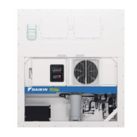
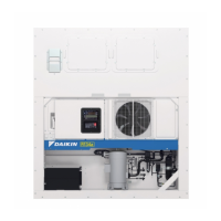
How to fix a Daikin LXE10E136 Refrigerator that does not operate?
- JJeff SullivanJul 27, 2025
If your Daikin Refrigerator isn't operating, here are a few things to check: * **Power Supply:** Ensure the power supply is working correctly, the plug is properly connected, and there are no cable disconnections. * **Condenser Fan:** Check if the condenser fan is running. If not, ensure it stops when high pressure is under control. Increase the high pressure and confirm the condenser fan stops when the HPT reaches 1000 kPa or more. * **Switch:** Make sure the power switch is turned ON. * **Fuse:** Inspect Fu1 (fuse) for any disconnections. * **Transformer:** Consider replacing the transformer.