3-2
3.2 Basic operation of electronic controller
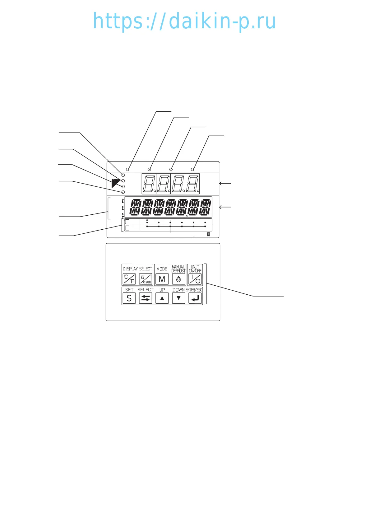
3.2.1 Control panel
Name and function of each components
q
t
y
u
i
w
e
r
o
!0
Sheet key
LED (Light Emitting Diode)
LCD (Liquid Christal Display)
3
1
2
c
–12 –10 –8 –6 –4 –2
–2–3–4–5–6 –1
SP–5
OVER
2
INRANGE
HOURS
DAYS
1
UNDER
ALARM
R.H.
SUPPLY
RETURN
˚C / ˚F
%R H
DEFROST INRANGE DEHUMID
COMP.
˚C
˚C
SP+5
DECOS
DAIKIN ELECTRONICCONTAINER OPERATION SYSTEM
q
SUPPLY LED (Lights when "supply air temperature" is indicated.)
w
RETURN LED (Lights when "return air temperature" is indicated.)
e ALARM LED (Blinks when alarm is generated.)
r R.H.LED (Lights when "relative humidity" is indicated.)
t COMP.LED (Lights when the compressor is running.)
y
DEFROST LED (Lights when the unit is under the defrosting operation.)
u
IN RANGE LED (Lights when the control temperature is in range.)
i DE-HUMID.LED (Lights when the controller is the
dehumidification control. (optional)
o Temperature base (Used for the graphic chart indication
on the LCD.)
!0
Time base (Used for the graphic chart indication on the LCD.)
03LXE10E100以降(1-12)E.qx08.8.275:18PMページ3-2