This document provides a comprehensive service manual for the Daikin Marine Type Container Refrigeration Unit, model LXE10E136GE, a dual-unit type. It covers essential information for operation, maintenance, and troubleshooting.
Function Description
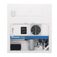
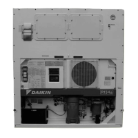
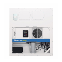
The Daikin LXE10E136GE is a marine type container refrigeration unit designed for maintaining specific temperature conditions within shipping containers. It operates as a dual-unit system, implying redundancy or the ability to switch between main and standby units for continuous operation. The unit utilizes a hot gas defrost system to prevent ice buildup on the evaporator coils, ensuring efficient cooling performance. Its control system allows for precise temperature management and includes various safety features to protect the unit and its contents. The system is designed for robust operation in marine environments, capable of handling different power supply configurations.
Important Technical Specifications
- Model: LXE10E136GE
- Refrigeration System: Air-cooled, dedicated for refrigeration.
- Controller: DECOS II g
- Power Supply:
- AC 3-phase: 380V/400V/415V at 50Hz
- AC 3-phase: 440V/460V at 60Hz
- Compressor: Hermetic scroll type with a motor output of 5.5kW.
- Evaporator: Cross fin coil type
- Air-cooled Condenser: Cross fin coil type
- Evaporator Fan: Propeller fan, driven by a 3-phase squirrel-cage induction motor.
- Condenser Fan: Propeller fan, driven by a 3-phase squirrel-cage induction motor.
- Defrost System: Hot-gas defrost system.
- Initiation: Timer, on-demand defrost, and manual switch.
- Termination: Timer, evaporator outlet pipe, and return air temperature.
- Refrigerant Flow Control: Electronic expansion valve.
- Capacity Control: Suction proportional valve and hot gas bypass for capacity modulation.
- Protective Devices:
- Circuit breaker, PT/CT board (for overcurrent protection).
- Compressor thermal protector.
- Condenser fan motor thermal protector.
- Evaporator fan motor thermal protector.
- High-pressure switch, fusible plug, fuse (glass tube fuse).
- Refrigerant (charged amount): R134a: 4.5 kg
- Refrigeration Oil (charged amount): IDEMITSU, Daphne hermetic oil FVC 46D
- Weight: 426 kg
- Temperature Recorder: Not provided (optional).
- USDA Receptacle: Located on the left side of the inside of the room.
- PC Port: Outside control box.
- Modem: Provided.
Usage Features
The LXE10E136GE is designed for straightforward operation with clear instructions for starting and switching between units.
- Starting Procedure:
- Set the "MAIN" position of the unit select switch (SEL) in both the main and stand-by units.
- Turn "OFF-MAIN" of the start switch (SSW) and "OFF" of the alarm switch (ALS) in both units.
- Connect the power plug to the electrical power source, and turn "ON" the switch of the power source.
- Turn "ON-MAIN" of the start switch (SSW) in the unit with a power plug connected.
- Set temperature controllers.
- Ensure no unusual noise and vibration.
- Turn "ON" the alarm switch (ALS) after the inside temperature of the container reaches below the set value (+15°C) of the thermostat for alarm buzzer.
- Dual Unit Operation (Stand-by unit operation):
- The unit supports a stand-by mode, allowing for continuous operation even if one unit experiences issues.
- To operate the stand-by unit, set the unit select switch (SEL) to "STAND-BY" position.
- Turn "OFF-MAIN / ON-STAND-BY" of the start switch (SSW).
- The stand-by unit will then start to run.
- The wiring diagram illustrates how the main and stand-by units are connected and how power is supplied to each.
- Alarm System: The unit includes an alarm system with a buzzer and lamp to indicate operational issues. The alarm thermostat is set to activate if the internal temperature exceeds +15°C.
- Safety Precautions: The manual emphasizes critical safety precautions, including ensuring the power cable of both main and stand-by units is not connected at the same time to prevent danger. It also warns against operating the unit ON/OFF switch without the sheet key and removing the cover plate without proper authorization.
Maintenance Features
The manual provides guidelines for maintenance and troubleshooting, ensuring the longevity and reliability of the unit.
- Controller Access: The unit's controller is accessible, allowing for adjustments and diagnostics.
- Cover Plate Removal: Instructions are provided for safely removing the cover plate for maintenance, including turning off the unit ON/OFF switch with the sheet key.
- Battery Mode: In battery mode, the unit ON/OFF setting should not be turned off.
- Controller Replacement: After replacing the controller, specific steps must be followed: remove the cover plate, turn on the snap switch, turn off the unit ON/OFF switch with the sheet key, turn off the snap switch, and return the cover plate to its original position.
- Parts List: The manual includes a comprehensive parts list (TR12-03) and a standard service manual (TR12-02) for ordering spare parts and detailed service procedures.
- Wiring Diagrams: Detailed wiring diagrams are provided for both the main unit and the stand-by unit, as well as for the main/stand-by change switch, which are crucial for electrical troubleshooting and maintenance.
- Regular Checks: The manual advises checking for unusual noise and vibration during operation, which can indicate potential issues.
- Thermostat Management: It is important not to change the thermostat setting unless necessary, as it is factory-set for optimal performance.
This detailed description highlights the key aspects of the Daikin LXE10E136GE, making it easier for users to understand its capabilities, operation, and maintenance requirements.