3-37
3.7 Controller replacement and software upgrade
3.7.1 Controller replacement
<Replacement procedure for the controller>
¡Always turn off the main power supply to the facility before carrying out the following procedures.
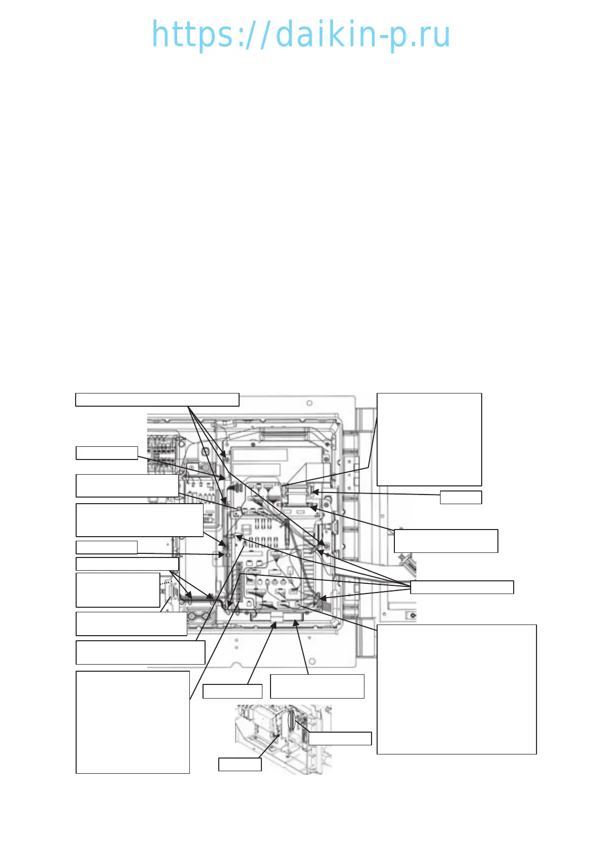
(1) Remove binding band q fixing each harness to the controller unit.
Remove binding band w binding harnesses.
→Take care not to damage the harnesses.
(2) Disconnect round solderless terminal e from the power supply I/O board.
Disconnect the harness of terminal No.139 from wire saddles r and t.
(3) Disconnect connector y from the CPU board and the harness from clamp u, respectively.
(4) Disconnect connector i from the CPU board and the harness from wire saddle r, respectively.
(5) Remove the Velcro tape !0 and remove dry cell battery or rechargeable battery !1.
→Properly store the removed battery for reuse.
(6) Disconnect connector !2 of the PT/CT board and the harness from clamp !3, respectively.
Pull out connector !2 from the inner side of the harness, and disconnect the harness from wire
saddle r.
(7) Disconnect connectors !4 to !6 from the CPU board and power supply I/O board.
→It is not necessary to disconnect the short-circuit connector or empty connector.
(8) Remove mounting screw (with washer) !7, mounting screw !8, spring washer !9 and toothed lock
washer @0 of the controller.
→Properly store the removed screws and washers for reuse.
Mounting screw !7 (with washer)×4 pieces
Mounting screw !8×1 piece
Spring washer !9×1 piece
Toothed lock washer @0×1 piece
Clamp !3
Harness bundle
(Refer to the figure below.)
Wire saddle t
Wire saddle r
Binding band w×2 pieces
Connector i (CPU board)
CN48 (BATTERY)
Connector !2 (PT/CT board)
CN2 (EC5)
Connector !6
(Power supply I/O board)
CN4 (optional :MODEM)
Velcro tape !0
Dry cell battery or
rechargeable battery !1
Round solderless terminal e
(Power supply I/O board)
103 (optional, T/F A2 cable)
108 (optional, T/F A2 cable)
123 (optional, T/F A2 cable)
125 (optional, T/F A2 cable)
131 (CTP)
132 (CTP)
139 (MTP)
140 (CFC)
Connector !4 (CPU board)
CN42 (optional :FAS)
CN43 (thermistor)
CN44 (LPT, HPT)
CN46 (optional :HuS)
CN47 (USDA, CTS)
CN50 (PPR1)
CN51 (PPR2)
CN52 (optional :MODEM)
Connector !5 (Power supply I/O board)
CN1 (Tr1)
CN3 (optional :RECORDER)
CN9 (SMV)
CN11 (EV2)
CN12 (RSV, BSV, DSV, HSV)
CN13 (ISV, ESV)
CN14 (LSV)
CN15 (HPS)
CN16 (RM)
CN17 (optional :WPS)
CN18 (optional :CBS)
CN19 (CC/RPP, EFH, EFL, PCC1, PCC2)
Clamp !3
Harness bundle
Binding band q×5 pieces
Connector y (CPU board)
CN41 (EC3)
Clamp u
03LXE10E100以降(33-41)E.qx08.8.2210:31AMページ3-37