IOM 1266-2 • MAGNITUDE
®
MODEL WME CHILLERS 50 www.DaikinApplied.com
operaTIon
Compressor Controller Inputs and Outputs
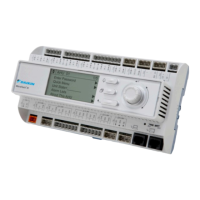
The following tables list, for each compressor controller, analog inputs and digital outputs as well as the stepper motor outputs.
Table 29: Compressor Controller, Analog Inputs
# Description Source Signal Sensor Range
1 Compressor Suction Temperature NTC Thermistor 10k @ 25°C -40 to 125°C
2 Compressor Discharge Temperature NTC Thermistor 10k @ 25°C -40 to 125°C
3 Suction Refrigerant Pressure Sealed Gage Transducer 0.5 to 4.5 VDC nominal 0 to 100 psi
4
Discharge Refrigerant Pressure Sealed Gage Transducer 0.5 to 4.5 VDC nominal 0 to 200 psi
5 Rotor Pump Temperature NTC Thermistor 10k @ 25°C -40 to 125°C
6 Inlet Guide Vane Position Rotary Transducer 1.5 to 2.6 VDC nominal Closed to Open
7 Motor Winding Temperature 1 NTC Thermistor 10k @ 25°C -40 to 150°C
8 Motor Winding Temperature 2 NTC Thermistor 10k @ 25°C -40 to 150°C
9 Motor Winding Temperature 3 NTC Thermistor 10k @ 25°C -40 to 150°C
10 Motor Case Temperature NTC Thermistor 10k @ 25°C -40 to 125°C
11 Motor Gap Temperature NTC Thermistor 10k @ 25°C -40 to 125°C
Table 30: Compressor Controller, Digital Outputs
# Description Load Output OFF Output ON
1 VFD Enable VFD Compressor OFF Compressor ON
2 Liquid Injection Solenoid (24 VDC, 20 VA max) No Injection Injection
3 Stator Cooling Solenoid (24 VDC, 20 VA max) Cooling OFF Cooling ON
Table 31: Compressor Controller, Analog Outputs
Description Output Signal Sensor Range
Inlet Guide Vane Driver Position 0 to 10 VDC 0 to 100%
Rotor Cooling Driver Signal 0 to 10 VDC 0 to 100%
PLBV Driver Position 0 to 10 VDC 0 to 100%
 Loading...


