OM 1239 27 www.DaikinApplied.com
typICal WIrIng dIagraMs
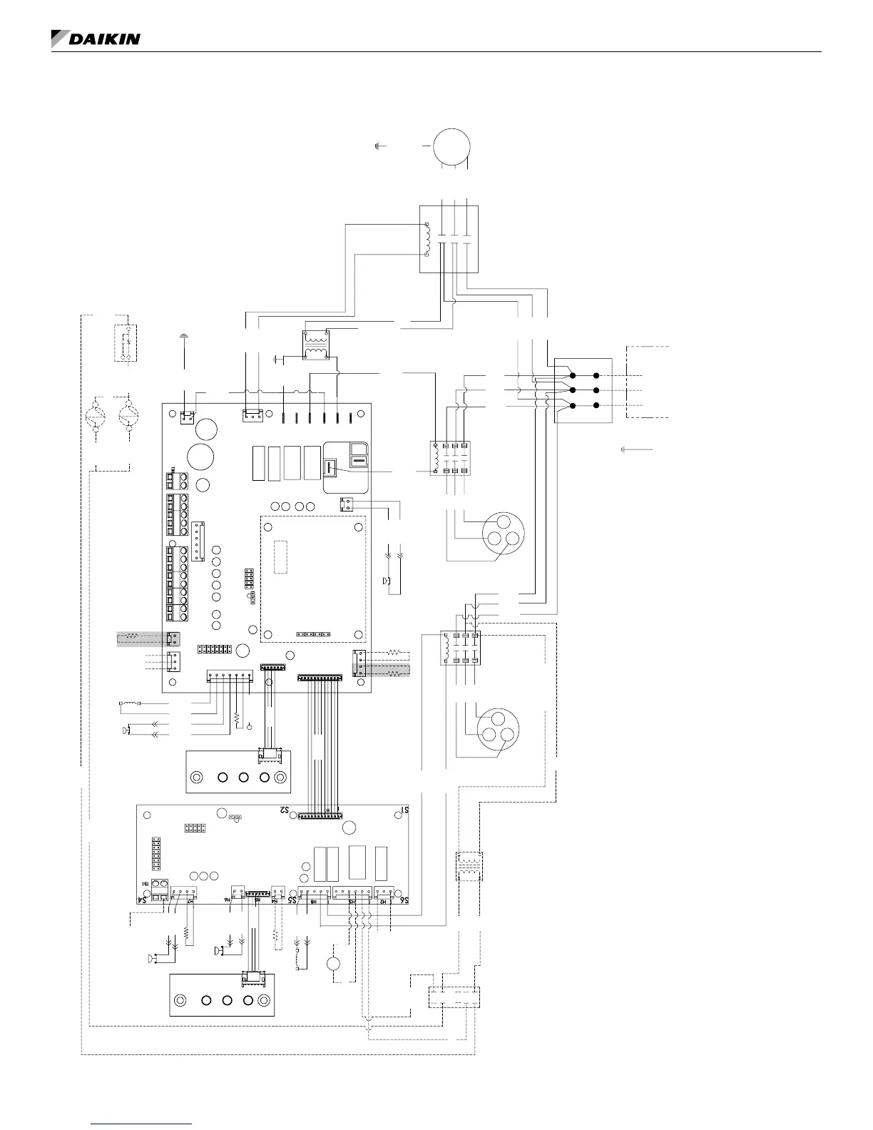
MicroTech III controller with I/O expansion module with hot gas reheat (HGRH)
208/230, 460, 575-60-3 (1.5 hp or less)
YEL 14
BLU 15
LED1
SLTS
RV
LED1
GRY 46
BLU 41
BLU 40
RAT
LED2
IOEXP
COS
BLK 60
BLK 61
SEE NOTE
BLU 21
LED2
T1
TB1
YEL
RED
L1
L2
L3
CM-1
BLK
L1
T2
T3
L3
L2
L1
SERVICE &
DISCONNECT
L3L2
YEL 18
JP_2
JP_3
JP_4
JP_5
JP_6
JP_7
JP_8
H1
H2
N3
N2
N1
L1-3
L1-2
L1-1
H3
H5
H4
H7
H6
H8
H9
TB2
TEST-1
TB1
TB3
RUN PRG
JTAG
BLU 20
LP2
HP2
SLTS2
1
1
1
1
1
JP1
JP8
JTAG
RV2
YEL 11
RED 12
CC1
BLK 1
YEL 2
RED 3
BRN 52
BRN 53
BLU 42
BLU 43
BLK 62
BLK 63
YEL 19
LP
T3
BLK 10
YEL 8 (L2)
RED 9 (L3)
R1
HP
BRN 55
BRN 54
GRN/YEL 97
FAN
MOTOR
LWT
DAT
YEL
BLU
YEL 45
EWT
BLK/RED-460V
RED-208V
ORG-230V
BLK-575V
1
RED 86
WHT 85
R2
1
3
BLK 80
YEL 82
HUMIDISTAT SIGNAL
AUX HEAT
24VAC COMMON
BLK 80
GND
JP_1
BLK 4
YEL 5
RED 6
YEL 27
BLU 28
CC2
RED
YEL
BLK
L3
L2
L1
X2
BLK
YEL
BLU
YEL 89
BLK 81
TB2
ORG 87 YEL 83
YEL 88
R2
2
54
ORG 84
H
HG1
HG2
H
N
24V
X1
COM
BLK
BLK/RED - 460V
RED - 208v
ORG - 230V
BLK - 575V
CM-2
BLK7 (L1)
IO Expansion Module
C - 24VAC COMMON
O - W3 - HEAT -3
G - FAN
Y1 - COOL - 1
Y2 - COOL 2
W1 - HEAT - 1
W2 - HEAT - 2
A - ALARM OUTPUT
5 - DC SIGNAL COM
4 - ROOM SENSOR/TO
3 - SETPOINT ADJUST
2 - FAN MODE/HT-CL-AUTO
1 - ROOM SENSOR LED
U - MARK IV - OCC/UNOCC
E - EMER SHTDN INPUT
R - 24VAC
Communication
Module
MicroTech III Controller
24V NO
24VAC COMMON
24V NC
Note: Switch L2/L3 fan
motor wires for
left-hand unit
Legend
Item Description
CC1
Circuit 1 Compressor Contactor
CC2
Circuit 2 Compressor Contactor
CM1
Circuit 1 Compressor
CM2
Circuit 2 Compressor
COS
Condensate Overow Sensor
HP
Circuit 1 High Pressure Switch
HP2
Circuit 2 High Pressure Switch
IOEXP
I/O Expansion Board / Harness
LED1
LED
Annunciator / Harness
LED2
LED
Annunciator / Harness
*RAT
Return Air
Temp Sensor
*LWT
Leaving W
ater Temp Sensor
LP
Circuit 1 Low Pressure Switch
LP2
Circuit 2 Low Pressure Switch
SL
TS
Circuit 1 Suction Line
Temp Sensor
SLTS2 Circuit 2 Suction Line Temp Sensor
R1
Fan Motor Starter
R
V
Circuit 1 Reversing V
alve Solenoid
RV2
Circuit 2 Reversing V
alve Solenoid
TB1
Power T
erminal Block
X1
75
VA Transformer
*DAT
Discharge Air
Temp Sensor
EWT
Entering W
ater Temp Sensor
R2
Relay HGRH
HG1
HGRH Solenoid 1
HG2
HGRH Solenoid 2
TB2
Terminal Block
X2
T
ransformer 24VAC Output
Note: Wiring diagrams are typical. For the latest
drawing version refer to the wiring diagram located on
the inside of the controls access panel of the unit.
Gray tinted areas in the wiring diagram: Units with fac-
tory installed communication module include Discharge
Air Temperature (DAT) and Return Air Temperature
(RAT) sensors shipped loose and are eld installed.
The Leaving Water Temperature (LWT) sensor is fac-
tory installed.
Notes: 1. “Run/Prg” Jumper to be in “Run”
position for normal operation
* Leaving Water (LWT), Discharge
Air (DAT) and Return Air
Temperature (RAT) sensors are
eld installed.
_ _ _ _
Denotes optional feature

 Loading...


