OM 1239 30 www.DaikinApplied.com
typICal WIrIng dIagraMs
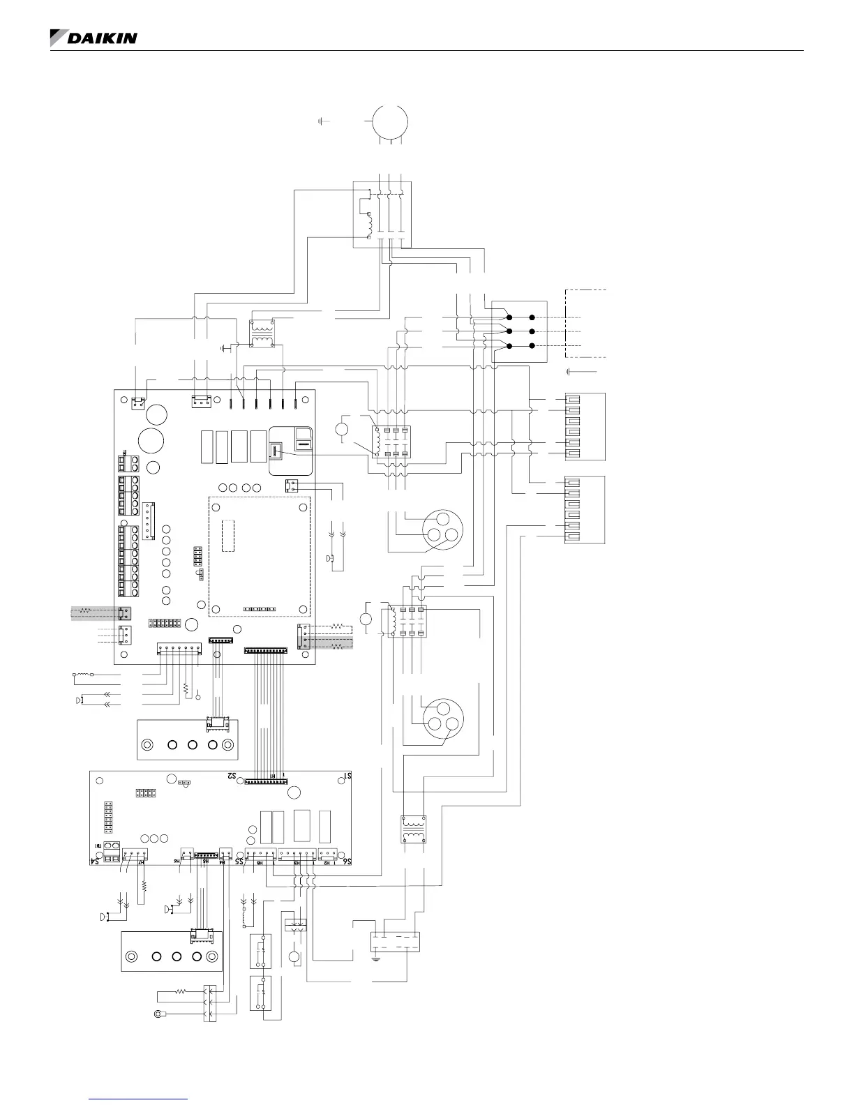
MicroTech III controller with I/O expansion module – with waterside economizer
208/230, 460, 575-60-3
COMPRESSOR
PROTECTOR
MODULE
T2
T1
S2
S1
M2
M1
COMPRESSOR
PROTECTOR
MODULE
T2
T1
S2
S1
M2
M1
LED1
SLTS
RV
LED1
GRY 46
BLU 41
BLU 40
RAT
LED2
IOEXP
COS
BLK 60
BLK 61
SEE NOTE
LED2
JP_2
JP_3
JP_4
JP_5
JP_6
JP_7
JP_8
H1
H2
N3
N2
N1
L1-3
L1-2
L1-1
H3
H5
H4
H7
H6
H8
H9
TB2
TEST-1
TB1
TB3
RUN PRG
JTAG
BLU 20
LP2
HP2
SLTS2
1
1
1
1
1
JP1
JP8
JTAG
RV2
YEL 11
RED 12
CC1
BRN 52
BRN 53
BLU 42
BLU 43
BLK 62
BLK 63
YEL 19
LP
BLK 10
YEL 8 (L2)
RED 9 (L3)
BLK 7 (L1)
R1
HP
BRN 55
BRN 54
GRN/YEL 97
FAN
MOTOR
LWT
DAT
BLK
BLU
YEL 45
BLK/RED-460V
RED-208V
ORG-230V
BLK-575V
1
JP_1
BLK 4
YEL 5
RED 6
YEL 27
BLU 28
CC2
YEL 34
BLK 33
L3
L2
L1
X2
BLK
YEL
BLU
YEL 89
BLK 81
TB2
RED
OL
T1
T2
L1
T3
L2
L3
COM
24V
X1
T1
TB1
L1
T2
L3
L2
L1
SERVICE &
DISCONNEW
L3
L2
BLK 1
YEL 2
RED 3
T3
GND
YEL 18
YEL 31
RED 32
L1
L2
L3
CM-1
BLK 30
CM-2
BLK/RED - 460V
RED - 208v
ORG - 230V
BLK - 575V
YEL
77
BLU
75
BLU
72
BLU
70
YEL
76
BLU
74
BLU
73
BLU
71
RED 35
YEL
BLU 15
YEL 14
45
2
R3
45
2
R4
87
86
TO GRY 46
10
11
85
WSE
M
EWT
COE
TO COS
R4
BLU
104
YEL
103
R3
YEL
101
BLU
102
IO Expansion Module
C - 24VAC COMMON
O - W3 - HEAT -3
G - FAN
Y1 - COOL - 1
Y2 - COOL 2
W1 - HEAT - 1
W2 - HEAT - 2
A - ALARM OUTPUT
5 - DC SIGNAL COM
4 - ROOM SENSOR/TO
3 - SETPOINT ADJUST
2 - FAN MODE/HT-CL-AUTO
1 - ROOM SENSOR LED
U - MARK IV - OCC/UNOCC
E - EMER SHTDN INPUT
R - 24VAC
Communication
Module
MicroTech III Controller
24V NO
24VAC COMMON
24V NC
Note: Switch L2/L3 fan
motor wires for
left-hand unit
Note: Wiring diagrams are typical.
For the latest drawing version refer
to the wiring diagram located on the
inside of the controls access panel of
the unit.
Gray tinted areas in the wiring dia-
gram: Units with factory installed com-
munication module include Discharge
Air Temperature (DAT) and Return Air
Temperature (RAT) sensors shipped
loose and are eld installed. The
Leaving Water Temperature (LWT)
sensor is factory installed.
Legend
Item Description
CC1
Circuit 1 Compressor Contactor
CC2
Circuit 2 Compressor Contactor
CM1
Circuit 1 Compressor
CM2
Circuit 2 Compressor
COS
Condensate Overow Sensor
HP
Circuit 1 High Pressure Switch
HP2
Circuit 2 High Pressure Switch
IOEXP
I/O Expansion Board / Harness
LED1
LED
Annunciator / Harness
LED2
LED
Annunciator / Harness
*RAT
Return Air
Temperature
*LWT
Leaving W
ater Temp Sensor
LP
Circuit 1 Low Pressure Switch
LP2
Circuit 2 Low Pressure Switch
SL
TS
Circuit 1 Suction Line
Temp Sensor
SLTS2
Circuit 2 Suction Line
Temp Sensor
MTIII
MicroT
ech III Main Board
R1
Fan Motor Starter
R
V
Circuit 1 Reversing V
alve Solenoid
RV2
Circuit 2 Reversing V
alve Solenoid
TB1
Power T
erminal Block
X1
75
VA Transformer
X2
50
VA Transformer
*DAT
Discharge Air
Temp Sensor
*EWT
Entering W
ater Temp Sensor
WSE
W
aterside Economizer
TB2
Power T
erminal Block
Notes: 1. “Run/Prg” Jumper to be in “Run” position for
normal operation
* Leaving Water (LWT), Discharge Air (DAT) and
Return Air Temperature (RAT) sensors are
eld installed.
_ _ _ _
Denotes optional feature

 Loading...


