3 | Components
Service manual
190
RXM20~71R + ARXM25~71R + FTXM20~71R + ATXM25~50R +
FVXM25~50A
Split New Perfera R32
ESIE20-11 – 2021.01
Name Symbol Location
(PCB)
Connector
(pins)
Inter-
mediate
connector
(pins)
Referen
ce
(table)
Discharge
pipe
thermistor
R3T Main (O/U) S90:5‑6 - A
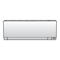
Wall mounted indoor units
Name Symbol Location
(PCB)
Connector
(pins)
Inter-
mediate
connector
(pins)
Referen
ce
(table)
Indoor unit
air (room)
thermistor
R1T Display PCB
A3P on
main PCB (I/
U)
S800:5‑11 S27:1‑2 on
display PCB
B
Heat
exchanger
thermistor
R2T Main (I/U) S501:1‑2 - A
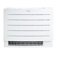
Floor standing indoor units
Name Symbol Location
(PCB)
Connector
(pins)
Inter-
mediate
connector
(pins)
Referen
ce
(table)
Heat
exchanger
thermistor
R1T Main (I/U) S501:1‑2 - A
Indoor unit
air (room)
thermistor
R2T Main (I/U) S501:3‑4 - A
Humidity
thermistor
R3T Humidity
sensor PCB
A5P on
main PCB (I/
U)
S600 CN on A5P -
4 Determine the thermistor resistance that matches the measured
temperature.
Thermistor – Table A
T °C kΩ T °C kΩ T °C kΩ T °C kΩ
–20 197.81 10 39.96 40 10.63 70 3.44
 Loading...