Table of Contents
Service manual
6
RXM20~71R + ARXM25~71R + FTXM20~71R + ATXM25~50R +
FVXM25~50A
Split New Perfera R32
ESIE20-11 – 2021.01
5.6 To clean the air filters ..................................................................................................................................................... 216
5.7 To clean the titanium apatite deodorising filter and the silver allergen removal air purifying filter ........................... 219
5.8 To replace the titanium apatite deodorising filter and the silver allergen removal air purifying filter........................ 220
6 Technical data 222
6.1 Detailed information setting mode ................................................................................................................................ 222
6.1.1 Detailed information setting mode: Indoor unit ........................................................................................... 222
6.1.2 Detailed information setting mode: Outdoor unit ........................................................................................ 222
6.1.3 Detailed information setting mode: Remote controller................................................................................ 222
6.2 Wiring diagram................................................................................................................................................................ 223
6.2.1 Wiring diagram: Indoor unit........................................................................................................................... 223
6.2.2 Wiring diagram: Outdoor unit........................................................................................................................ 229
6.3 Piping diagram ................................................................................................................................................................ 234
6.3.1 Piping diagram: Indoor unit............................................................................................................................ 234
6.3.2 Piping diagram: Outdoor unit......................................................................................................................... 238
6.4 Component overview...................................................................................................................................................... 242
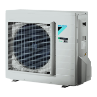
6.4.1 Component overview: Outdoor unit.............................................................................................................. 242
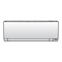
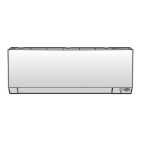
6.4.2 Component overview: Wall mounted indoor unit......................................................................................... 244
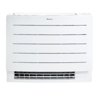
6.4.3 Component overview: Floor standing indoor unit ........................................................................................ 246
6.5 Field information report ................................................................................................................................................. 247
6.6 Service tools .................................................................................................................................................................... 250
6.7 Field settings ................................................................................................................................................................... 251
6.7.1 To control heating only mode........................................................................................................................ 251
6.7.2 To adjust target set temperature in heating operation ................................................................................ 251
6.7.3 To control the indoor unit fan during thermostat off in cooling................................................................... 252
6.7.4 To change auto restart ON to OFF ................................................................................................................. 253
6.7.5 To limit the angle of the upper swing flap ..................................................................................................... 253

 Loading...


