EasyManuals Logo

Daikin R-410A Service Manual

Daikin R-410A
381 pages
To Next Page IconTo Next Page
To Previous Page IconTo Previous Page
Page #137 background imageLoading...
Page #137 background image
ESIEN05-04 PCB Layout
Part 1 – System Outline 1–119
3
1
4
5
6.12 FAQ71B
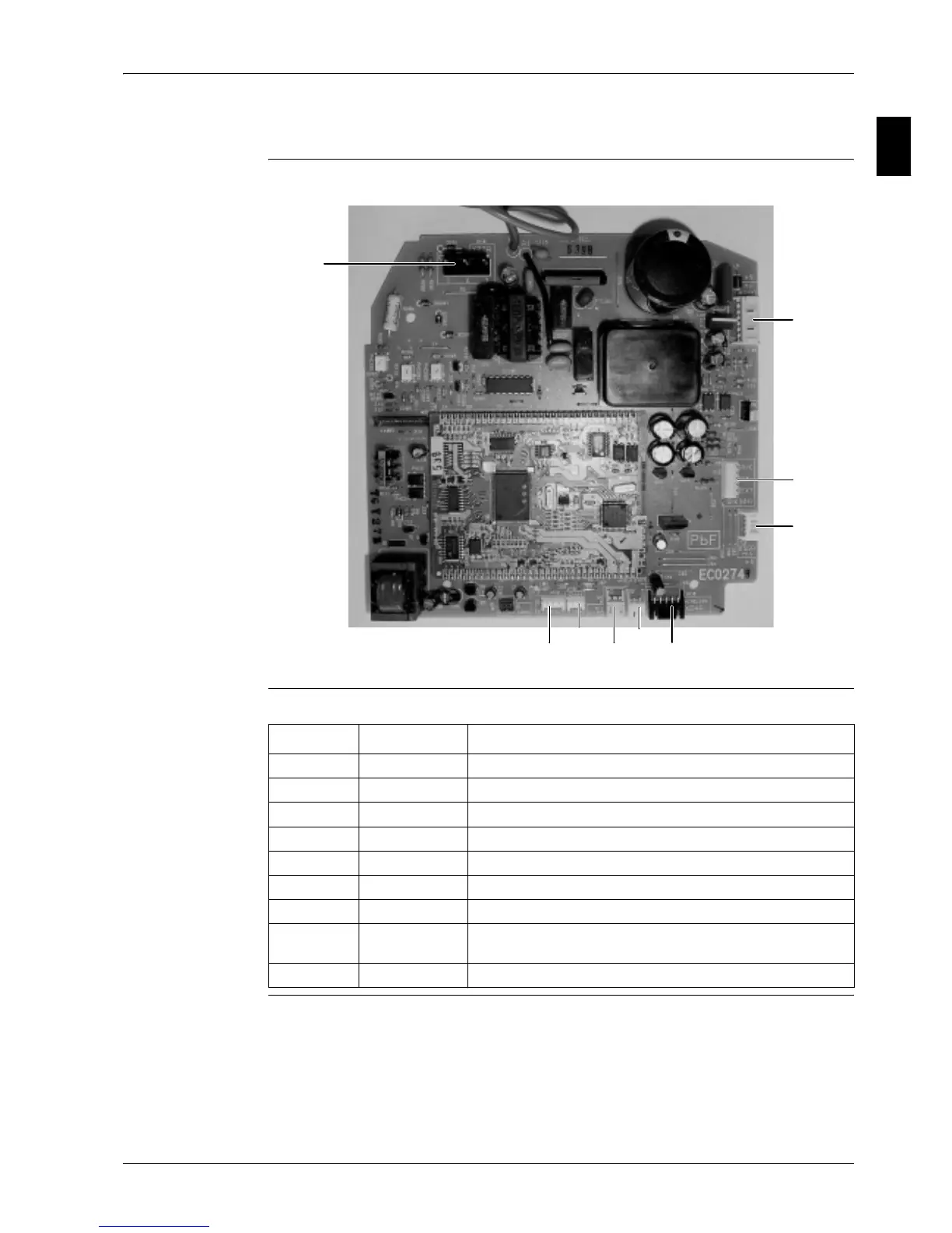
PCB The illustration below shows the PCB connectors.
Connectors The table below describes the PCB connectors.
X27A
X20A
X30A
X36A
X19A
X18A
X15A
X35A
X24A
Connector Connected to Description
X15A Connector float switch
X18A R2T Coil thermistor (liquid)
X19A R1T Air thermistor
X20A M1F Fan motor (power supply)
X24A X2A on A2P infrared remote control connector
X27A X2M Power supply & communication
X30A X1M Terminal strip for P1/P2
X35A X1A on KRP4 Connector to group control adapter power supply (16 VDC) for
optional PCB KRP4
X36A M1S Swing flap motor

Table of Contents

Other manuals for Daikin R-410A

Questions and Answers:

Question and Answer IconNeed help?

Do you have a question about the Daikin R-410A and is the answer not in the manual?

Daikin R-410A Specifications

General IconGeneral
BrandDaikin
ModelR-410A
CategoryAir Conditioner
LanguageEnglish

Related product manuals