Do you have a question about the Daikin RQYQ140-180PY1 and is the answer not in the manual?
Essential safety precautions and warnings for handling and repairing the equipment.
Lists model series, names, and power supply for indoor and outdoor units.
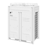
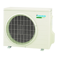
Visual representation of various outdoor unit configurations and their corresponding HP ratings.
Details system capacity and number of units for heat pump and heat recovery series.
Connectable indoor units number and capacity for heat pump and heat recovery series.
Technical specifications for outdoor units, including cooling/heating capacity, dimensions, and components.
Specifications for BSVQ100, 160, 250PV1 and BSV4Q100, 6Q100PV1 BS units.
Lists and describes components in the refrigerant system diagram for specific outdoor units.
Identifies key components and their locations in the plan and front view of the outdoor unit.
Illustrates refrigerant flow paths during different operational modes for specific outdoor units.
Provides an overview of system operation modes and control functions.
Explains specific control functions such as stop, standby, rotation, startup, normal, protection, and special operations.
Outlines the procedures for initial test operations after installation.
Step-by-step procedure for checking operation and refrigerant charging for specific models.
Lists and explains various field setting items configurable via dip switches and push buttons.
Provides a guide to diagnose and resolve issues based on system symptoms and supposed causes.
Explains how to use the remote controller for inspection, self-diagnosis, and service modes.
Guides on how to put the system into test run mode for operational checks.
Lists various malfunction codes, their content, and corresponding page references for detailed troubleshooting.
Addresses issues related to reverse phase or open phase in the power supply.
Troubleshooting for transmission errors between indoor and outdoor units.
Troubleshooting for transmission issues between main and sub remote controllers.
Resolving issues related to duplicated addresses in centralized controllers.
Visual representations of refrigerant piping for outdoor and BS units.
Electrical wiring diagrams for outdoor and BS units.
Lists available option parts for outdoor units.
Provides guidance on connecting outdoor units, BS units, and indoor units with piping details.