Do you have a question about the Daikin RX20J3V1B and is the answer not in the manual?
Details safety precautions for repair work, classified into Warning and Caution items.
Explains the meaning of icons used to attract reader attention to specific information.
Lists and describes various functions of the air conditioner unit.
Provides detailed technical specifications for indoor and outdoor units.
Details the PCB and connector wiring for the indoor unit.
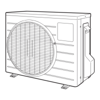
Details the PCB and connector wiring for the outdoor unit.
Details the primary functions of the air conditioner, such as temperature control and frequency.
Explains how the unit controls room temperature based on thermistor readings.
Describes how compressor frequency is controlled for capacity regulation.
Details how airflow direction is controlled using flaps and louvers.
Explains the 9 steps of fan speed control and automatic adjustment.
Describes humidity removal and temperature control during dry operation.
Explains how the unit automatically determines cooling or heating mode.
Details thermostat control based on room thermistor and target temperature differences.
Enhances comfort and conserves electricity during sleep by adjusting temperature.
Reduces operating current and power consumption for energy saving.
Maximizes cooling/heating capacity by increasing fan speed and compressor frequency.
Provides instructions on how to set the clock on the remote controller.
Covers functions like Hot-Start, Signal Receiving Sign, ON/OFF button, and filters.
Explains the role of different thermistors in controlling the unit's operations.
Outlines the various control specifications and logic for unit operation.
Defines the hierarchy of operation modes: normal, forced, and test modes.
Explains how frequency is determined based on temperature differences and PI control.
Details control actions during mode changes and start-up, including preheating and valve switching.
Manages compressor frequency based on discharge pipe temperature for protection.
Sets frequency upper limits based on input current to protect the compressor.
Prevents indoor heat exchanger freezing during cooling operation by limiting frequency.
Limits frequency during heating to prevent abnormal high pressure.
Describes various conditions for controlling the outdoor fan's operation and speed.
Protects the compressor by stopping it under specific outdoor temperature conditions.
Manages the defrosting cycle using reverse cycle operation.
Details the control logic for the electronic expansion valve in different operation modes.
Covers sensor malfunctions, overcurrent/overload detection, and refrigerant shortage.
Describes the remote controller's display, buttons, and signal transmission.
Guides troubleshooting based on blinking operation lamps and service monitor LEDs.
Lists common symptoms and corresponding measures for diagnosis and repair.
Explains how to use the remote controller for service check and error code display.
Provides detailed error codes and troubleshooting procedures for various system faults.
Lists all error codes, their descriptions, and corresponding reference pages.
Details troubleshooting steps for indoor unit PCB abnormalities (Error Code A1).
Troubleshoots freeze-up or peak-cut control errors (Error Code A5).
Guides troubleshooting for abnormal fan motor operation (Error Code A6).
Troubleshoots thermistor errors in the indoor unit (Error Codes C4, C9).
Explains methods for detecting and troubleshooting refrigerant shortage (Error Code U0).
Covers troubleshooting for voltage detection errors (Error Code U2).
Troubleshoots signal transmission errors between indoor and outdoor units (Error Code U4).
Addresses issues with unspecified voltage between units (Error Code UA).
Details troubleshooting for outdoor unit PCB abnormalities (Error Code E1).
Diagnoses and resolves compressor overload issues detected by the OL protector (Error Code E5).
Provides troubleshooting steps for compressor lock faults (Error Code E6).
Troubleshoots DC fan lock errors detected by fan motor rotation speed (Error Code E7).
Addresses input overcurrent detection issues (Error Code E8) related to compressor running.
Details troubleshooting for four way valve abnormalities based on thermistor readings (Error Code EA).
Troubleshoots errors related to discharge pipe temperature control (Error Code F3).
Addresses high pressure control issues in cooling mode (Error Code F6).
Troubleshoots compressor system sensor abnormalities (Error Code H0).
Details troubleshooting for compressor start-up position sensor failures (Error Code H6).
Covers DC voltage/current sensor abnormalities (Error Code H8).
Troubleshoots thermistor errors in the outdoor unit (Error Codes H9, J3, J6, P4).
Troubleshoots electrical box temperature rise issues detected by the fin thermistor (Error Code L3).
Addresses radiation fin temperature rise issues detected by the fin thermistor (Error Code L4).
Diagnoses output overcurrent detection in the inverter DC section (Error Code L5).
Provides procedures for checking components and system operation.
Details how to measure thermistor resistance values for diagnosis.
Guides checking fan motor connector output, voltage, and rotation pulse.
Explains how to check power supply waveforms for disturbances.
Details the procedure for checking the electronic expansion valve's functionality.
Describes how to check the performance of the four way valve.
Outlines checks for the refrigerant system in inverter units.
Explains how to use an inverter analyzer for diagnosis.
Details checking rotation pulse input on the outdoor unit PCB.
Checks installation conditions like airflow, cleanliness, and dimensions.
Guides how to check the discharge pressure for diagnosing issues.
Details how to check the outdoor fan system.
Explains how to check for short circuits in the main circuit.
Details how to check the power module's resistance.
Covers essential servicing tips like pump down and forced cooling operations.
Guides the process for conducting trial operation after servicing.
Explains field settings, including multi-unit installation and jumper configurations.
Details the correct application of silicon grease on power components for heat dissipation.
Provides piping diagrams for indoor and outdoor units.
Includes wiring diagrams for indoor and outdoor units.
References specific booklets for unit removal procedures.
| Model | RX20J3V1B |
|---|---|
| Category | Heat Pump |
| HSPF | 10 |
| Voltage (V) | 230 |
| Refrigerant | R32 |
| Energy Efficiency Ratio (Cooling) | 3.5 |
| Coefficient of Performance (Heating) | 4.0 |
| Noise Level (Indoor Unit) | 19 dB |
| Heating Capacity (BTU) | 20, 000 |
| Power Supply | 1 Phase, 50 Hz |
| Dimensions (Outdoor Unit) | 780 x 285 x 540 mm |