• Outdoor Units • R-410A • RXG-E2V1B
7
• Split Sky Air • Outdoor Units
12
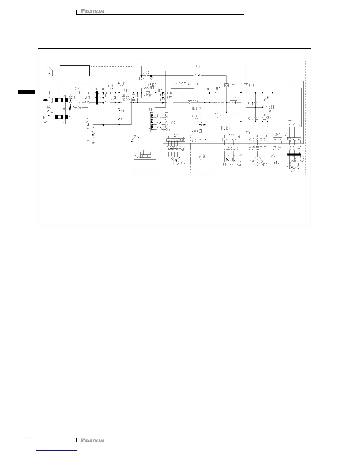
7 Wiring diagram
7 - 1 Wiring diagram
3D042576H
RXG25-35E
R
: Protective earth
C74, C75
C94, C95, C100 : Capacitor
DB1, DB2 : Diode bridge
FU1, FU2, FU3 : Fuse
LC11 : Solid state relay
LPM1 : Intelligent power module
L : Live
L1 : Coil
L1R : Reactor
M1C : Compressor motor
M1F : Fan motor
MRCW,
MRM10, MRM20 : Magnetic relay
N : Neutral
PCB1, PCB2 : Printed circuit board
Q1L : Overload protector
R1T, R2T, R3T, S10 : Thermistor
S11, S20, S30, S40
S70, S80, S90, S91
HC3, HC4, HL3, HN3 : Connector
SA1 : Surge arrester
Z1C, Z2C : Ferrite core
X1M : Terminal strip
V1, V2, V3 : Varistor
Y1E : Electronic expansion valve coil
Y1R : Reversing solenoide valve coil
g
Field wiring
Indoor
Outdoor
(outdoor)
(Condenser)
(discharge)
In case of heat pump
type
In case of cooling
only type
Note
1. Refer to the name plate for the power requirements.