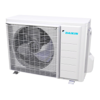
Do you have a question about the Daikin RXL12QMVJU and is the answer not in the manual?
Provides warnings and cautions for worker safety during repair and maintenance.
Explains the meaning of icons used throughout the manual for clarity.
Details the changes and versions of the manual.
Lists all indoor and outdoor unit models covered by this manual.
Details the available functions for various model series.
Provides detailed technical specifications for indoor and outdoor units.
Wiring diagrams for various indoor unit models.
Wiring diagram for the wireless remote controller receiver.
Wiring diagram for the wired remote controller.
Wiring diagrams for various outdoor unit models.
Wiring information for optional accessories.
Describes general functions like temperature control and frequency principle.
Details specific functions for FTX and FVXS series units.
Details specific functions for FDMQ series units.
Explains the role and function of various thermistors in the system.
Outlines system control logic, frequency control, and protection mechanisms.
Lists remote controllers compatible with different unit series.
Details the features and operation of the ARC466A21 remote controller.
Details the features and operation of the ARC466A37 remote controller.
Details the features and operation of the ARC480A8 remote controller.
Details the features and operation of the BRC082A43 remote controller.
Details the features and operation of the BRC1E73 remote controller.
Lists common symptoms and initial checks for troubleshooting.
Explains how to diagnose issues using LED indicators on indoor/outdoor units.
Provides methods for diagnosing system faults using remote controllers.
Lists all error codes, their descriptions, and reference pages for troubleshooting.
Detailed troubleshooting steps for specific errors in FTX/FVXS series.
Detailed troubleshooting steps for specific errors in FDMQ series.
Detailed troubleshooting steps for outdoor unit related errors.
Procedure for safely removing refrigerant when relocating or disposing of the unit.
Procedure for forcing the unit into cooling operation for testing.
Steps for conducting trial operation to verify system functionality.
Configuration settings for FTX and FVXS series units.
Configuration settings for FDMQ series units.
Configuration settings for outdoor units.
Guidance on applying silicone grease during PCB replacement.
Schematic diagrams showing refrigerant piping for indoor units.
Schematic diagrams illustrating electrical connections for indoor units.
Details the operational temperature limits for cooling and heating modes.
| Cooling Capacity (BTU) | 12000 |
|---|---|
| Cooling Capacity (kW) | 3.52 |
| Cooling Capacity (Ton) | 1 |
| Heating Capacity (kW) | 3.6 |
| Energy Efficiency Rating | A++ |
| SEER | 6.1 |
| HSPF | 3.8 |
| Energy Efficiency Ratio (Heating) | 3.6 |
| Refrigerant | R-32 |
| Power Supply | 230V/1Ph/50Hz |
| Indoor Unit Noise Level | 19 dB |
| Type | Split System Air Conditioner |


