EasyManua.ls Logo

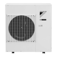
Daikin RXS36HVJU User Manual

Daikin RXS36HVJU
202 pages
To Next Page IconTo Next Page
Page #1 background imageLoading...
Page #1 background image
Service
Manual
Inverter Pair
Wall Mounted Type H-Series
SiUS04-924_A
[Applied Models]
Inverter Pair : Cooling Only
Inverter Pair : Heat Pump

Table of Contents

Other manuals for Daikin RXS36HVJU

Questions and Answers:

Daikin RXS36HVJU Specifications

General IconGeneral
BrandDaikin
ModelRXS36HVJU
CategoryAir Conditioner
LanguageEnglish

Summary

Service Manual

Inverter Pair Wall Mounted Type H-Series

Details the Inverter Pair Wall Mounted Type H-Series service manual.

Applied Models

Lists applied models for the service manual.

Part 1 List of Functions

Safety Considerations

Essential safety considerations for operating and servicing the unit.

Functions

Outlines the various functions available for the unit.

Part 2 Specifications

Specifications

Provides detailed technical specifications for the unit.

Cooling Only / 60 Hz, 208 - 230 V

Technical specifications for cooling-only models at 60 Hz, 208-230 V.

Heat Pump / 60 Hz, 208 - 230 V

Technical specifications for heat pump models at 60 Hz, 208-230 V.

Part 3 Printed Circuit Board Connector Wiring Diagram

Indoor Unit

Details PCB connectors and parts for the indoor unit.

Outdoor Unit

Details PCB connectors and parts for the outdoor unit.

Part 4 Function and Control

Main Functions

Explains the primary functions and operational modes of the unit.

Temperature Control

Details how the unit controls and maintains room temperature.

Frequency Principle

Explains the principle of frequency control for the compressor.

Airflow Direction Control

Describes how airflow direction is managed and adjusted.

Fan Speed Control for Indoor Unit

Details the fan speed control mechanisms for the indoor unit.

INTELLIGENT EYE Operation

Describes the INTELLIGENT EYE function for detecting human presence.

Inverter POWERFUL Operation

Explains the Inverter POWERFUL operation for maximum capacity.

Function of Thermistor

Explains the role and function of various thermistors in the system.

Control Specification

Specifies the control logic and parameters for various operations.

Mode Hierarchy

Outlines the hierarchy of operation modes for the unit.

Frequency Control

Details the frequency control logic for compressor operation.

Part 5 Operation Manual

System Configuration

Provides an overview of system configuration and initial setup.

Operation Manual

Details how to operate the air conditioner.

Remote Controller

Explains the parts and usage of the remote controller.

AUTO · DRY · COOL · HEAT · FAN Operation

Describes how to use the AUTO, DRY, COOL, HEAT, and FAN modes.

Adjusting the Airflow Direction

Guides on adjusting the airflow direction for comfort.

COMFORT AIRFLOW Operation

Explains the COMFORT AIRFLOW operation for comfortable air distribution.

INTELLIGENT EYE Operation

Details the INTELLIGENT EYE operation for energy saving.

POWERFUL Operation

Describes the POWERFUL operation for enhanced cooling/heating.

ECONO Operation

Details the ECONO operation for efficient power consumption.

WEEKLY TIMER Operation

Guides on setting up weekly timer schedules for the unit.

Part 6 Service Diagnosis

Troubleshooting with LED

How to troubleshoot using LED indicators on the units.

Problem Symptoms and Measures

Lists common symptoms and their corresponding solutions.

Service Check Function

Explains how to use the service check function via the remote.

Troubleshooting

Detailed troubleshooting steps for various error codes.

Error Codes and Description

Lists all error codes and their descriptions with page references.

Indoor Unit PCB Abnormality

Troubleshooting steps for indoor unit PCB abnormalities.

Freeze-up Protection Control or Heating Peak-cut Control

Troubleshooting for freeze-up or heating peak-cut control issues.

Fan Motor (DC Motor) or Related Abnormality

Troubleshooting for fan motor (DC motor) related abnormalities.

Thermistor or Related Abnormality (Indoor Unit)

Troubleshooting for thermistor abnormalities in the indoor unit.

Signal Transmission Error (between Indoor Unit and Outdoor Unit)

Troubleshooting for signal transmission errors between units.

Outdoor Unit PCB Abnormality

Troubleshooting steps for outdoor unit PCB abnormalities.

OL Activation (Compressor Overload)

Troubleshooting for compressor overload (OL activation).

Compressor Lock

Troubleshooting steps for compressor lock issues.

Refrigerant Shortage

Troubleshooting for refrigerant shortage detection.

Low-voltage Detection or Over-voltage Detection

Troubleshooting for low-voltage or over-voltage detection.

Check

Procedures for performing various checks on components.

Thermistor Resistance Check

How to check thermistor resistance values.

Electronic Expansion Valve Check

Procedure for checking the electronic expansion valve.

Installation Condition Check

Verifying installation conditions for proper operation.

Part 7 Removal Procedure

Indoor Unit

Step-by-step instructions for removing indoor unit components.

Removal of Air Filters / Front Panel

Procedure for removing the air filters and front panel.

Removal of Front Grille

Steps for detaching and removing the front grille.

Removal of Electrical Box

Instructions for safely removing the electrical box.

Removal of PCBs

Procedure for removing various Printed Circuit Boards (PCBs).

Removal of Fan Motor

Steps for removing the fan motor assembly.

Removal of Indoor Heat Exchanger

Detailed process for removing the indoor heat exchanger.

Outdoor Unit

Step-by-step instructions for removing outdoor unit components.

Removal of Outer Panels

Procedure for removing the outer panels of the unit.

Removal of Electrical Box

Instructions for safely removing the outdoor unit's electrical box.

Removal of PCBs

Procedure for removing PCBs from the outdoor unit.

Removal of Fan Motor

Steps for removing the outdoor unit's fan motor.

Removal of Coils / Thermistors

Procedure for removing coils and thermistors.

Removal of Compressor

Detailed steps for removing the compressor.

Part 8 Trial Operation and Field Settings

Pump Down Operation

Procedure for pump down operation before relocating or disposing the unit.

Forced Cooling Operation

Instructions for performing forced cooling operation.

Trial Operation

Steps to perform trial operation after installation.

Field Settings

Configuration settings for specific installation environments.

Model Type Setting

Setting the remote controller for heat pump or cooling-only models.

Temperature Display Switch

Changing the temperature display unit between Fahrenheit and Celsius.

When 2 Units are Installed in 1 Room

Altering settings for dual indoor unit installations.

Facility Setting Switch (cooling at low outdoor temperature)

Expanding cooling range for low outdoor temperatures.

Jumper and Switch Settings

Information on jumper and switch settings for various functions.

Part 9 Appendix

Piping Diagrams

Diagrams illustrating the refrigerant piping of the unit.

Indoor unit

Piping diagram for the indoor unit.

Outdoor Unit

Piping diagrams for the outdoor unit models.

Wiring Diagrams

Electrical wiring diagrams for the unit's components.

Related product manuals