EasyManua.ls Logo

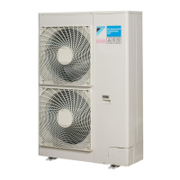
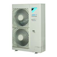
Daikin RXYSQ4P8Y1B User Manual

Daikin RXYSQ4P8Y1B
36 pages
To Next Page IconTo Next Page
Page #1 background imageLoading...
Page #1 background image
INSTALLATION MANUAL
RXYSQ4P8V1B
RXYSQ5P8V1B
RXYSQ6P8V1B
RXYSQ4P8Y1B
RXYSQ5P8Y1B
RXYSQ6P8Y1B
System air conditioner

Table of Contents

Question and Answer IconNeed help?

Do you have a question about the Daikin RXYSQ4P8Y1B and is the answer not in the manual?

Daikin RXYSQ4P8Y1B Specifications

General IconGeneral
BrandDaikin
ModelRXYSQ4P8Y1B
CategoryAir Conditioner
LanguageEnglish

Summary

3. Before Installation

R410A Precautions, Installation, and Handling

Covers R410A safety, installation references, and unit handling.

4. Selecting Installation Site

Site Selection Criteria and Windy Location Considerations

Guidelines for choosing an installation site and precautions for windy areas.

5. Precautions on Installation

Preventing Unit Falling and Removing Transportation Stay

Methods to secure the unit and remove transportation stays.

6. Installation Servicing Space

Servicing Space for Stacked and Non-Stacked Installations

Details on required space for different installation types.

7. Refrigerant Pipe Size and Allowable Length

7.1. Selection of Piping Material

Guidelines for selecting appropriate piping material and thickness.

8. Precautions on Refrigerant Piping

Brazing and Flare Connection Cautions

Best practices and warnings for brazing and flare pipe connections.

9. Refrigerant Piping Handling and Usage

Foreign Object Prevention and Stop Valve Operation

Measures to prevent foreign objects and how to handle stop valves.

9.4. Cautions for Valve Cover and Service Port Handling

9.6. Field Piping and Insulation Precautions

9.7. Example Connection for Sky Air/Room AC

Refrigerant Branch Kit and Pipe Size Selection

Pipe Size Selection and Refnet Joint Example

9.8. Example Connection for VRV Units

VRV Branch Kit, Pipe Size, and Connection Cautions

Guidance on VRV branch kits, pipe sizing, and connection precautions.

Refrigerant System Checks and Information

9.12. Field Settings for BP Unit

9.13. Procedures for Adding Refrigerant

Procedure 1: Automatic Refrigerant Charging

Step-by-step guide for automatic refrigerant charging.

Procedure 2: Charging While Outdoor Unit is Standstill

Procedure 3: Charging While Outdoor Unit is Operating

10. Electrical Wiring Work

10.1. Internal Wiring - Parts Table

Table listing internal wiring components and their symbols.

10.2. Precautions on Electrical Wiring Work

10.3. System Wiring Connection Examples

10.4. Connecting Power and Transmission Wires

10.5. Power Circuit and Cable Requirements

11. Before Operation

11.1. Service Precautions

Safety precautions to take before performing service.

11.2. Checks Before Initial Start-up

11.3. Field Setting

Switch and LED Operation/Location

How to operate switches and identify locations of LEDs/buttons.

Setting Operating Modes

Procedure for changing operating modes using switches and buttons.

Setting Mode Configurations and Function Options

Details on setting modes 1, 2, confirmations, and function options (A-F).

11.4. Test Operation

Remote Controller Error Codes and Troubleshooting

Lists error codes and their remedial actions.

11.5. Checks in Normal Operation

11.6. Temperature Adjustment Operation Confirmation

Cautions for Normal Operation Check

12. Service Mode Operation

Vacuuming and Refrigerant Recovery Methods

Procedures for vacuuming and recovering refrigerant in service mode.

13. Caution for Refrigerant Leaks

13.1. Introduction and Safety Standards

Importance of safety against leaks and applicable standards.

13.2. Maximum Concentration Level Calculation

Defining and calculating maximum allowable refrigerant concentration.

13.3. Procedure for Checking Maximum Concentration

Refrigerant Amount and Concentration Calculation

Steps to calculate refrigerant amount and concentration for compliance.

14. Disposal Requirements

Related product manuals