5 Commissioning
Installation manual
9
RZAG35~60A2V1B
R32 split series
3P548265-1 – 2018.08
g S70 – fan motor lead wire
4.5.1 Specifications of standard wiring
components
Component RZAG35A,
RZAG50A
RZAG60A
(a)
Power supply
cable
Voltage 220~240V
Phase 1~
Frequency 50Hz
Wire sizes 3-core cable
2.5mm
2
~4.0mm
2
H05RN-F (60245 IEC 57)
Interconnection cable
(indoor↔outdoor)
4-core cable
1.5mm
2
~2.5mm
2
and applicable
for 220~240V
H05RN-F (60245 IEC 57)
Recommended field fuse 16A 20A
Earth leakage circuit breaker MUST comply with applicable
legislation
(a) Electrical equipment comply with EN/IEC 61000-3-12.
(European/International Technical Standard setting the
limits for harmonic currents produced by equipment
connected to public low-voltage systems with input current
>16A and ≤75A per phase.)
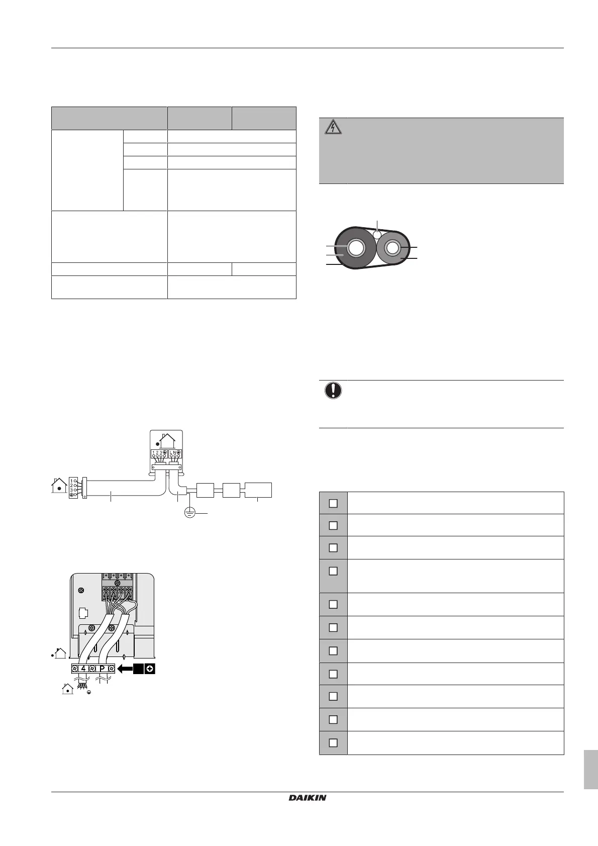
4.5.2 To connect the electrical wiring on the
outdoor unit
1 Remove the switch box cover.
2 Open the wire clamp.
3 Connect the interconnection cable and power supply as follows:
a Interconnection cable
b Power supply cable
c Field fuse
d Earth leakage circuit breaker
e Power supply
f Earth
4 Tighten the terminal screws securely. We recommend using a
Phillips screwdriver.
5 Install the switch box cover.
4.6 Finishing the outdoor unit
installation
4.6.1 To finish the outdoor unit installation
DANGER: RISK OF ELECTROCUTION
▪ Make sure that the system is earthed properly.
▪ Turn off the power supply before servicing.
▪ Install the switch box cover before turning on the power
supply.
1 Insulate and fix the refrigerant piping and interconnection cable
as follows:
a Gas pipe
b Gas pipe insulation
c Interconnection cable
d Liquid pipe
e Liquid pipe insulation
f Finishing tape
2 Install the service cover.
5 Commissioning
NOTICE
NEVER operate the unit without thermistors and/or
pressure sensors/switches. Burning of the compressor
might result.
5.1 Checklist before commissioning
After the installation of the unit, first check the following items. Once
all below checks are fulfilled, the unit MUST be closed, ONLY then
can the unit be powered up.
The indoor unit is properly mounted.
The outdoor unit is properly mounted.
The system is properly earthed and the earth terminals
are tightened.
The fuses or locally installed protection devices are
installed according to this document, and have NOT been
bypassed.
The power supply voltage matches the voltage on the
identification label of the unit.
There are NO loose connections or damaged electrical
components in the switchbox.
There are NO damaged components or squeezed
pipes on the inside of the indoor and outdoor units.
There are NO refrigerant leaks.
The refrigerant pipes (gas and liquid) are thermally
insulated.
The correct pipe size is installed and the pipes are
properly insulated.
The stop valves (gas and liquid) on the outdoor unit are
fully open.
 Loading...